


AN EPICYCLIC GEARBOX WITH GATE CHANGE.
Page 28
If you've noticed an error in this article please click here to report it so we can fix it.
A Résumé of Recently Published patents.
• Specification No. 154,113 by Jno.
' Arthur describes a gearbox of the epicyclic type which is -controlled by the ordinary form of change-speed „lever working in the 'familiar gate queeirant. There-ere several unusual features about this gearbox, and it is well worth serious study.
Assillustrated in t the patent speeificas 'ion it provides four speeds of which the top gear is direct. No provision appears to be made in the design as described for a reverse gear, although this could obviously quite easily be incorporated without interfering with the patented features of the box.
Tbe main driving shaft runs right through the centre of the box. It carries three pinions placed near to one another and all of different sizes. The gearbox itself is bored to accommodate three internal-toothed gearwheels, which are turned on their external surfaces so that they. will revolve in the bored portion of the box. These internal-toothed gears are the outer Wheels of the three epicyclic gears which go to form the box, and they are disposed so as to be in alignment with the three pinions on the driving shaft to which we have already referred. Planetary pinions of the usual type intervene between the pinions on the 'driving shaft and the outer wheels, and these -pinions are all carried by a substantial .spider which serves as the driven member of this gearbox. The planetary pinion& are free to revolve upon their journals in the spider.
Conveniently situated on top of the box are three plungers disposed so that each is opposite to one of the outer -Wheels of the gear. In the peripheries of the latter are positioned a number of recesses with Which these plungers may engage. The plungers are controlled by springs and a change-speed lever working, in conjunction. .There are two springs to each plusiger, one being somewhat stronger than the other. On. 'depression of the outer cap of the plunger by means of the change-speed lever the strong spring. is compressed, and this leaves the weaker one free' . to operate upon the plunger so that, immediately a recess in the gearwheel appears opposite to it, the plunger engages with that recess and holds the wheel itself stationary. There is a fourth plunger which acts upon one arm of a bell-crank lever. The other arm is forked, and bears uponThe collar
of the double dog clutch. Normally, this clutch is only in engagement with the planetary spider or driven member of the gearbox. Upon depression of the plunger in question, however, the clutch engages also with teeth formed upon the driving shaft, the transmission is then a direct one, and this forms the top gear. There are two horizontal locking levers freely 'pivoted upon a pin, ohe of them engages at its ends with two of the spring plungers, the other, a long one, engages the other two plungers. A change-speed lever working in the usual form of gate, selects one or other of these locking levers and then, by a forward or reverse movement, depresses One or other of the plungers into engagement with its corresponding gearwheel. The usual precautions are taken to ensure that no two gears are engaged Simultaneously. B20
Other Patents of Interest.
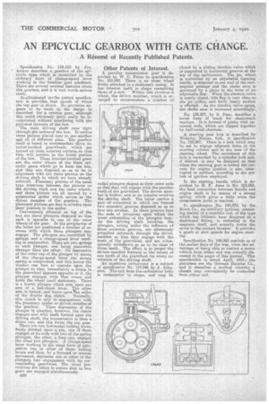
A peculiar transmission gear is described by W. G. Pitter in specification No 153,982. There is an outer wheel firmly attaChed to a stationary casing. It has internal teeth in shape resembling those of a saw. Within this revolves -a wheel, the driven member, which is arranged to accommodate a number oi
radial plungers shaped at their outer ends so that they will engage with the peculiar teeth of the gearwheel. The driven member is hollow, and in its interior revelves the driving shaft. The latter carries a pair of eccentrics, in ivhich are. formed two eccentric grooves disposed so as to face one another'. In these grooves bear the on& of trunnions -upon which the inner extremities of the plungers bear. As the driving shaft revolves, the plungers, acting under the influence of these eccentric grooves, are alternately propelled outwards through the driCen member so that they engage with the teeth of the gearwheel, and are selasequently withdrawn to as to be clear of those teeth. The effect is to propel the driven member forward to the extent of one tooth of the gearwheel for every revolution of the driving shaft. An ingeatious earburetter is a subject of specification No. 154.046 by J. Johnelem. The exit, from the carburetter body rectangular. in shape, and may be
• closed by a sliding throttle valve which is supported in horizontal grooves at the top of the carburetter. The jet, which is controlled by an adjustable tapering needle, is disposed in one wall of the rectangular passage and the choke area is governed by a plane in the form of an adjustable flap. When the throttle valve is nearly closed, this flap is very close to the jet orifice, and fairly heavy suction is effected. As the throttle valve opens, the choke area is increased accordingly.
No. 139,507,_by S. Faso, describes a -novel form' of track for chairetreektractors. It is formed of plates with upturned ende, which are clipped together by half-round channeLs.
A steering gear lock is described. by Wolseley Motors, Ltd., in specification No. 153,967. 'There is a bolt which may he. set to engage adjacent holes in the steering column and in the boss of the steering _wheel. Themovement of this bolt is controlled by a -cylinder lock and, if desired, it may be designed so that whenthe steering gear, is' locked the current, for engine ignition is also interrupted or earthed, according to the sys-, tern of ignition employed.
In the starting handle which is described by H. F. Anna in No. 153,993, the final connection between' handle and engine shaft is by means of a strong spring, which gives a little when the compression point is reached.
In specification 'No. 140,375, by the Bosch Co., an auxiliary ignition, consisting mainly of a t.,rnbier coil, of the type which has hitherto been designed as a dashboard fitting, is embodied in the magneto itself, and actually forms the cover to the contact breaker. It provides a spark at slow speeds for engine starting.
Specification No.' 148,365 reminds us of the-earlier days of the war, when the advantage of being able to control a motor vehicle from either end was actually discussed in the pages of this journal. This specification is dated. April, 1915; the patentees are the German Daimler Co., and it describes a method whereby a chassis may oonveniently be controlled from either end.