


Ideas for Improving the Electric Vehicle
Page 36
If you've noticed an error in this article please click here to report it so we can fix it.
A Re'surne of Patent Specifications That Have Recently Been Published
TWO patents from E. Kny;•4-; Dean's and the Associated Equipment ' Co.;
Yard, London, S.W.1, disclose an . improyed silent type of reduction gear for the drive of electric vehicles, also a form of transverse independent suspension for the frdnt wheels.
The first patent, No. 557,554, refers to the springing system; this coinpri-ses a transverse leaf spring secured to the central tubular chassis member (2). As the spring rises under load,. it abuts against a curved plate (1), which takes an increasing portion of the load as the length of contact increases. At the outer end, a shackle (3) is fixed to the master leaf and is pivoted on to the steering head (4). The upper end of the latter is linked to the frame by a pair of swinging radius arms (5). All • the pivotal points may be bushed with • rubber, which not only avoids the need for lubrication, but provides a blight torsional spring effect.
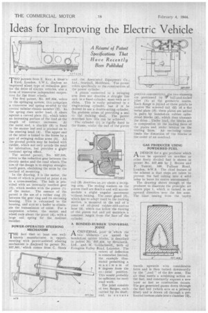
The second patent, No. 537,555, refers to the reduction gear between the electric motor, and the road wheels. The aim of the design is to employ straighttooth gears, abolishing the noise by the
method of mounting. '
In the drawing, 3 is the motor, the frame of which is pivoted at point 4 on to a cross-member. The hub is provided with an internally toothed gear (5), which meshes with the pinion (1) of the motor. The essence of the • patent is the use of a rubber ring (2) between the gear ring and its enclosing housing. This is vulcanized to the housing, and acts as a buffer to eliminate the transmission of nbise, For a suspension scheme, the motor and wheel rock about the pivot (4), with a large coil spring for the._ .resilient member.
POWER-OPERATED' STEERING MECHANISM:
THE fact that at least one wellknown manufacturer is experimenting with power-assisted steering mechanism is disclosed by patent No. 557,561, which comes from . G. Stock
• Ltd., ,Southall, Middlesex, The patent -refers specifically to the-construction of the power cylinder.
• A piston connected to a swinging arm does not describe a straightline and, in a fixed -cylinder, must rbek as it slides. This is easily permitted in a single-acting -cylinder, but if it be desired to use a double-acting cylinder, the problem arises of providing „a, seal to the rOcking shaft. The patent describes how this can be aehieved.
Thecylinder (1) is rigidly fixed to the frame, whilst the end of the piston rod (3):describes an arc'about a swinging arm.. The sealing washers on the piston itself are flexible and will accommodate a slight angular movement -without leaking. The outer, gland (2), which has to adapt itself to the rocking. motion, is mounted in the end of *a Piece -of oil-proof rubber-and-cadvas -hose (4), which can folio* the. rocking of the: piston. rod and, yet maintain a constant length from the face -.or the. cylinder.
A BONDED-RUBBER UNIVERSAL JOINT 'A ',UNIVERSAL' joint in ^which• the PI two. erefnents are • united by bonded-on, rubber blocks, is described 'in patent o. 557,424, by Metalastik, Ltd and M: Goldscbinidt„ both of EvingtOn Valley Read, Leicester. -The extent of deflection is somewhat limited, the example illustrated permitting a maximum of 9 degrees from the co axial position. This.would probably be sufficient for most road work.
en •
The joint consists of two flanges, each carried by. its shaft, 5.57,562 and, to ensure positive concentricity lie two -elements are positioned by tr ball-and-socket joint (1) at the geometric centre. Each flange is drilled at three points to receive the screwed. tail -(2) of a flat metal plate (3); these plates are united in pairs by bonded-on rubber cylindrical blocks (4), which thus transmit the drive. Under load, the blocks are in compression on the leading faces of the plates and under tension on the trailing faces. An 'enclosing 'cover limits the distortion -of the blocks, in the event of an overload.
GAS PRODUCER USING POWDERED FUEL
PAA DESIGN for a gas producer which can be operated on sawdust or other finely divided fuel is shown in parent No. 557,468 by J. Brown and P. Tamini, 169, Fulham Road, London, StW.3. The chief feature of the scheme is that steps are' taken to prevent the fuel caking into a solid luinp to leave its centre unconsumed.
The drawing shows enough of the producer to illustrate the principle; air enters pipe 1, which, is turned in an upward direction near the fire zone. The blast issuing from the tuyere travels upwards with considerable force and is then turned downwardly by the roof " of the Are zone. The air thus exerts a scrubbing action on the fuel, and constantly exposes a new layer as fast as combustion occurs. The gas generated passes down through the fuel bed (which acts as a primary filter). and is drawn off through a perforated bottom plate into a chamber (2).