


A Meat-carrying Body
Page 84
If you've noticed an error in this article please click here to report it so we can fix it.
PATENT No. 821,156 shows a body for transporting carcases or any Other load that can be' suspended from overhead rails. -The basis of the patent is a rearward extension of the .rails to facilitate loading and discharge. (Marsden (Coachbuilders), Ltd:, Bewsey, Warrington, Lancs.) ,' Referring to the drawing, the roof carries three rails (1). Each rail is provided with a rearward extension piece (2) vhich pivots about a hinge (3). The ffitee extensions are attached to a bridge member. (4)' with a. hydraulic ram •(5) at each side of it., • The rams swing the -extensions through 180'. degrees.
The drawing shows the device in the loading position. The carcases are placed on' travelling hooks (6) and the rains are thenused to lift'the' extensions tothe horizontal, in which position the. loaded .hooks can be run into the body. When the body is loaded, the extensions are'swung down and in that position act as a stop to the movement of the load. If the extensions are swung inwards, to lie against the roof interior,. the body is left clear for cleaning or for other loads.
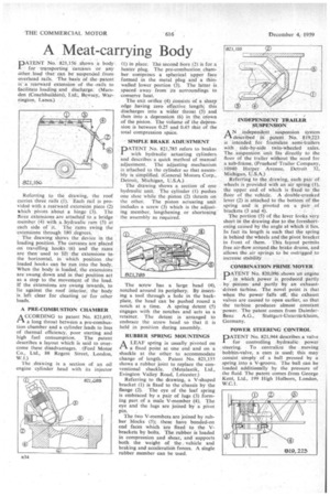
A PRE-COMBUSTION CHAMBER
A CCORDING to patent No. 821,693, .1-3. a long throat between a pre-combustion chamber and a cylinder leads to loss of thermal efficiency, poor starting and high fuel consumption. The patent describes a layout which is said to overcome these disadvantages. . (Ford Motor Co., Ltd., 88 Regent Street, London, W.1.) The .drawing is a section of an oil engine cylinder head with its injector
(I) in place. The second bore (2) is for a heater plug. The pre-combustion, chamber comprises a spherical upper face formed in the metal plug and a thinwalled lower portion (3). The latter is .spaced away from its surroundings to conserve heat.
The exit orifice (4) .consists of a sharp edge having zero effective length; this discharges into a wider throat (5) and then into a depression (6) in the crown of the piston. The volume of the depression is between 0.25 and 0.45 that of the total compression space.
SIMPLE BRAKE ADJUSTMENT DATENT No. 821,785 refers to brakes with hydraulic actuating cylinders and describes a quick method of manual adjustment. The adjusting mechanism is attached to the cylinder so that assembly is simplified_ (General Motors Corp., Detroit, Michigan, U.S.A.) The drawing shows a section of one hydraulic unit. The cylinder (1) pushes one shoe while the piston (2) thrusts on the other. The piston actuating unit includes a screw (3) which is the adjusting member, lengthening or shortening the assembly as required.
The screw has a large head (4), notched around its periphery. By inserting a tool through a hole in the backplate, the head can be pushed round a notch at a time. A spring detent. (5) engages with the notches and acts as a retainer. The detent is arranged to embrace the screw head so that it is held in position during assembly.
RUBBER SPRING MOUNTINGS
ALEAF spring is usually pivoted on a fixed point at one end and on a shackle at the other, to accommodate change of length. Patent No. 821,155 shows a rubber joint to replace the conventional shackle. (Metalastik, Ltd., Evington Valley Road, Leicester.)
Referring to the drawing, a V-shaped bracket (1) is fixed to the chassis by the flange (2). The eye of the leaf spring is embraced by a pair of lugs (3) forming part of a male V-member (4). The eye and the lugs are joined by a pivot pin.
The two V-members are joined by rubber blocks (5); these have bonded-on end faces which are fixed to the Vbrackets by bolts. The rubber is loaded in compression and shear, and supports both the weight of the, vehicle and braking and acceleration forces. A single rubber member can be used. INDEPENDENT TRAILER SUSPENSION AN independent suspension system described iri patent No. 819,223 is intended for frameless semi-trailers with side-by-side twin-wheeled axles. The suspension unit fits directly to the floor of the trailer without the need for a sub-frame. (Fruehauf Trailer Company, 10940 Harper Avenue, Detroit 32, Michigan, U.S.A.) • Referring to the drawing, each pair of wheels is provided with an air spring (I), the upper end of which is fixed to the floor of the vehicle. A double-cranked lever (2) is attached to the bottom of the spring and is pivoted on a pair of brackets (3 and 4).
The portion (5) of the lever looks very short in the drawing due to the foreshortening caused by the angle at Which it lies. In fact its length is such that the spring is behind the wheels and the pivot bracket in front of them. • This layout permits free air-flow around the brake drums, and allows the air springs to be outrigged to increase stability COMBINATION PRIME MOVER
PATENT No. 820,096 shows an engine in .which power is produced partly by pistons and partly by an exhaustdriven turbine. The novel point is that when the power falls off, the exhaust valves are caused to open earlier, so that the turbine produces almost constant 'power. The patent comes from DaimlerBenz A.G., Stuttgart-Unterttirkheim, Germany.
POWER STEERING CONTROL
PATENT No. 821,944 describes a valve for controlling hydraulic power steering. To centralize the moving bobbin-valve, a cam is used; this may consist simply of a ball pressed by a spring into a V-groove. The ball can be loaded additionally by the pressure of the fluid. The patent comes from George Kent, Ltd., 199 High Holborn, London, W.C.1.