


A Claudel Three-jet Carburetter
Page 58
If you've noticed an error in this article please click here to report it so we can fix it.
A Resume of Recently Published Patent Specifications
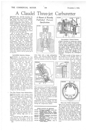
PATENT No. 455,708 describes the latest practice in carburetter design, and bears the name C. H. Claude), Veuxhaulles, Cote d'Or, France. The layout incorporates three jets for different conditions, and a two-fuel float arrangement with distributing valve.
In the drawing, the float-chamber
(11) feeds the petrol, whilst a second chamber (1) supplies heavier oil, a piston-valve (7) controlling the choice of fuel to only the main jet.
Jet 9 is for slow running, and delivers emulsified petrol-air, via tube 2, to the induction pipe. A second jet (10), also for petrol, feeds an annular space (3) around the main tube, where, during slow running, fuel accumulates ready for acceleration. Other annular spaces (4 and 5) also provide a small storage for the same purpose. The sizes of the orifices leading to these spaces are chosen to ensure successive operation and, ultimately, to direct the full-power suction on to the main tube, which is fed by petrol jet 8 or oil jet 6.
Anti-dribble Injection Scheme.
N jETHODS of unloading the line 1V1pressure in injection systems seem to be exercising the minds of inventors, and another scheme to this end is shown in patent No. 455,778 by Bryce, Ltd., Kelvin Works, Hackbridge, and others. The means adopted is to incorporate, in the delivery side of the pump, a high-lift valve plunger, the upper portion (1) of which is cylindrical, whilst the main body is provided with flats or grooves (3). A small-bore by-pass (2) is drilled in the housing, and is subject to the same pressures as the valve.
In operation, an ejection of fuel from the pump lifts the plunger high enough to clear part 1 and thus pass the fuel,
the by-pass being too small to deal with the discharge. When the pump
pressure is relieved, the plunger first returns quickly, creating a suction effect in the line, and then sinks slowly into its seating as the fuel is forced out of space 4, via the by-pass.
. Two New Patents from Daimler-Benz.
DiFYICULTIES with cylinder liners L./having flanged ends are mentioned in patent No. 455,324, by Daimler-Benz A.G., Stuttgart, Germany. The troubles in the past have been due to overheating of the portion of the bore immediately under the flange, and the present invention is intended to overcome this difficulty. The proposal is to locate the clamping shoulder (1) at the lower end of a relatively long
• cenical portion. By this means it is possible to conduct the cooling water to the point of greatest heating, that is, the upper seating edge next to the gasket.
A second patent. No. 455,340, by the same concern, deals with a means for pre-heating the air-charge of an oil engine, to permit the use of tar-oil and B24
This comprises a perforated cylindrical plug (2) embedded in a heat-insulating cup (1). Above this plug is a second similar, but thinner, perforated ring (3) arranged so that the fuel spray cannot impinge on the lower ring. A heating coil (4) is located in the chamber, but care is taken to position it so that it is clear of the spray.
The plug (2) reaches an incandescent temperature during working, and this serves to pre-heat the incoming charge during the compression stroke. Gas-producer Control System.
objection to suction-gas plants,
as usedon vehicles, is that during idling periods the producer is liable to cool off, which results in an insufficient gas supply being available when the throttle is opened. To overcome this difficulty is the object of the scheme shown in patent No, 454,695 by E. Fabritius, Annegatan 5a, Ilelsingfors, Finland.
The chief novelty of the scheme is the location of the throttle valve between the blower and the engine, so that at low engine speeds air continues to be drawn through the producer although the resulting gas is in excess of requirements, The surplus is allowed to escape into the atmosphere, and the inventor states that the improved acceleration more than compensates for the loss of fuel.
Three-shoe Brake Arrangement.
TO render almost the whole periphery of a brake drum effective is one of the objects of the design shown in patent No. 455,718 by L. H. Dimond, The Haven, Beryl Grove, Bristol. A pair of shoes (3) is spread by a conventional cam, but freely pivoted at their upper ends to a third shoe (2). This shoe is housed in parallel guides (I) on the back plate, and can move in only a radial direction ; this occurs when the lower pair is operated by the cam.