


BOLTS AND NUTS.
Page 33
If you've noticed an error in this article please click here to report it so we can fix it.
Our Driver and Mechanic Readers Relate How to Fasten them Securely.
TN THE 'THREE letters which we 1.p:11)1i-soh this week on the subject of bolts and nuts, two driver correspondents tell us how, when in place, these things may be properly secured, while a third tells us how to remove those which have stuck fast, and to insert those which will not so readily enter their due and proper places. Each is practical and useful; and we cannot, therefore, fairly award any extra, prize money to any one of the writers, but are taking the course of dividing the spoils, as it were, equally between them.
In the majority of cases the driver or mechanic has no access to special locking devices. If he has need Of such a 'thin,* he must invent it and, most likely, make it himself.
This is clearly what has happened more than once to "H.H.," of Highgate, who has sent us the accompanying series of sketches illustrating some simple .means of achieving this very definable end of ensuring that a nut, once fastened, shall stay so until such time as it is required to he removed.
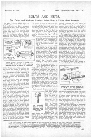
For the device 'which is illustrated by Fig. I, a plain steel washer is used, and must. be, in the first place annealed so
that there 'shall be no danger of its breaking while undergoing the treatment to which, for this present purpose, it has to he subjected. Four pairs of sawf-tuta are made in the washer as shown. One portion of metal between a pair of these cuts is turned down at, right-angles to its original position, and a bole 3S drilled in the sin-face of the material against which the nut should bed to. accommodate this turned-down piece of washer. When about tofit the nut, slip the washer over the bolt, with the projecting tongue registering with the hole, as shown in Fig. 2. Screw the not down hard, and turn up another piece of Metal—any one of The remaining three, as rtiajbe convenient—against a. face of the nut—and that. job's done, not to be undone until required. In a case in which a lack-nut is customarily employed, use a similar washer between the two nuts, and, after they have been properly locked together, turn two or more of the projections .up or dawn, as shown in Fig. 3. For the latter purpose a plain square washer, uncut, but properly annealed, may be used, as illustrated by Fig. 4 of the sketch.
Old Fastmit washers from which the spring clip is miasing may be used, in emergency, by hammering up against the side of the nut the projecting tongue to which that clip is ordinarily secured. (See Fig. 5. When there are two nuts fairly close together, as in the case of spring clips, then a piece of plain hoop iron, long enough to accommodate both bolts, may be used, as shown in Fig. 6, the ends of the iron being turned up against the faces of the nuts. In the case of spring bolts, however, these should not be regarded as permanently locked until the vehicle has travelled some hundreds of miles after its receipt from the manufacturers Or repairers, as the case may be.
In a communication which we published in February of last year
of Eye, Suffolk, made some suggestions concerning the design of coach screws and bolts, his object being to. improve them in a way which would eliminate the tendency to turn when a nut is being removed or replaced. These bolts are made, as a rule, with round cup-shaped heads and square shanks, and it is intended that the fit of the square shank in the roand hole should prevent the bolt from turning. Nodoubt it would have that effect were the thole always of the right size, and if, having been drilled the right size in the first plate, it would invariably remain so.
As it, does not always so remain, however, and is sometimes even drilled too large, it frequently happens that this type of bait turns just when it should not. Moreover, it. is nearly always the case that the bolt head is inaccessible, and even when accessible it is difficult to hold. In the former letter this writer suggested that the underside of the head should he provided with projecting points, which would embed themselves in the wood and thus prevent the objectionable twisting. He now improves upon that suggestion by
picskt
111
en An improved type of coach bolt used with success by
putting forward an idea which is clearly illustrated by the accompanying sketch, which shows a washer with a square hole in the middle, designed to engage the hole -in the bolt, and having projections to secure it to the wooden surface of the piece which the bolt is intended to hold.
The suggestions which are contained
in the letter from " of Ivybridge,' are concerned with the removal and insertion of intractable studs. Fig. I, for -example, of his sketches shows a tool designed to facilitate the withdrawal of studs from a casting. It consists of a flat steel bar—a short tyre lever about /1 in. thick is suitable— cranked as shown. It is drilled and tapped near each end, the holes being of various sizes, in accordance with the dimensions of the studs in connection with which it is to be used. When about to remove a stud, commence by screwing the bar on to it, following it up by the nut belonging to the stud, and screwing that nut tightly down on to the bar, as in the case of a lack-ant. Turn the bar' in the appropriate direction and the stud will follow. •
For inserting studs, use a square or hexagonalt block like that -depicted in
the sketch, tapped the same size as the stud. A hardened setscrew is inserted at one end of the hale in the block, and a cop-per washer separates this setscrew Irons the stud. Put, the stud into the block, and screw the setscrew and topper washer into close contact, then insert the other end of the stud into its destined hole, and turn by using a spanner on the block. An alternative method of withdrawing tight studs is shown in Fig. 3. Take a net to fit the stud and remove the threads, drilling, filing or reamer-log its interior until it is a close fit on to the plain -body of the -stud. Then file a taper notch in the hole as shown, and make a steel wedge or cotter to El,. Tighten .the nut an the stud by means of the .cotber, and withdraw the stud by turning the nut with a spanner in the ordinary way.