


TWO CHASSIS FOR MEDIUM LOADS.
Page 19
Page 20
If you've noticed an error in this article please click here to report it so we can fix it.
Interesting Details of the New 30-cwt. and 2-ton Maudslay Models.
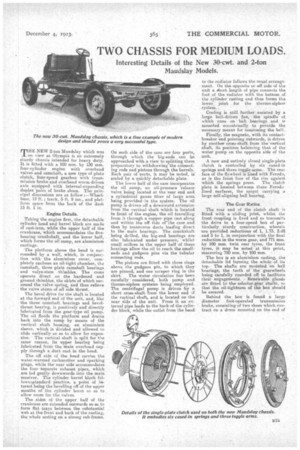
MHE NEW 2-ton Maudslay which was
on view at Olympia is an extremely sturdy chassis intended for heavy duty. It is -fitted with a 100 mm. by 130 mm. four-cylinder engine with overhead valves and camshaft, a new type of plate clutch, four-speed gearbox with tranemission brake and overhead worm-driven axle equipped with internat-expanding duplex pairs of brake shoes. The principal dimensions are as follow :—Wheelbase, 12 ft.; track, 5 ft, 9 ins.' and platform space from the back of the dash 15 ft. 1 in.
Engine Details.
Taking the engine first, the detachable cylinder head and barrel black are made of cast-iron, while the upper half of the crankcase, which accommodates the fivebearing crankshaft, and the lower half, which forms the oil sump, are aluminium castings.
The. platform above the head ia surrounded by a wall, which, in conjunction with the aluminium cover, completely encloses an MI-tight chamber, the camshaft, three plain camshaft hearings and valve-stem thimbles. The cams operate direct on the hardened and ground thimbles, the skirts of which surround the valve sprine. and thus relieve the valve stems of all side thrust.
The bevel drive for the Shaft is located at the forward end of the unit, and, like the three camshaft bearings and bevelthrust hearing, is positively and directly lubricated from the gear-type oil pump. The oil floods the platform and drains back into the sump by means of the vertical shaft housing, an aluminium sleeve, which is divided and-allowed to slide vertically so as to allow for expansion. " The vertical shaft is split for the Same . reason, its 'Titer bearing being lubricated from the main overhead supply through a duct cast in the head.
The off side of the head carries the water-warmed carburetter and sparking plugs, while the near side accommodates the four separate exhaust, pipes, which are led gently downwards into the main receiver. The cylinder barrel -Meek follows-standard practice, a point of interest being the bevelling off of the upper mouths of the cylinder bores so as to allow room for the valves.
The sides of the upper half of the crankcase are extended outwards so as to -.form flat trays between the subStantial web at the front and back of the casting, the whole resting on a strong sub-frame.
On each side of the case are four ports, through which the big-ends can be approached with a view to splitting them preparatory to withdrawing-the connecting rods and pistons through the barrels. Each pair of ports, it may he noted, ii sealed by a quickly detachable plate.
The lower half of the case incorporates the oil sump, an oil-pressure -release valve being located at the rear end and a cylindrical gauze filter of large area being provided, in the system. The ail pump is driven off a downward extension from the vertical shaft which is located in front of the engine, the oil travelling from it through a copper pipe cast along and within the off side orthe case and then by transverse duets leading direct to the main bearings. The _crankshaft being drilled, the big-end bearings are also lubricated under pressure, whilst small orifices in the upper half of these bearings allow the oil to reach the smallends and gudgeon pins via the tubular connecting rods.
The pistons are fitted with three rings above the gudgeon pin, to which they are pinned, and one scraper ring in the
skirt. The water circulation has been carefully considered, both pump and thermo-rsiphon systems being employed. The centrifugal pump is driven by a short cross-shaft from the lower end af the vertical shaft, and is located on the near side of the unit. From it an e.x. ternal pipe leads to the back of the cylinder block, while the outlet from the head to the radiator follows the usual arrangement. On the opposite or off side of the unit a short length of pipe connects the foot of the radiator with the bottom of the cylinder casting and thus forms the lower joint. for the therrno-siphon system,
Cooling ie still further assisted by a large belt-driven fan, • the spindle of which rims on • ball bearings and is mounted eccentrically to provide the necessary means for tensioning the belt.
Finally, the magneto, with itscontactbreaker end pointing outwards, is driven by another cross-shaft from the vertical shaft, its position balancing that of the water pump on the opposite side of the unit.
A new and eatirely closed single-plate clutch is controlled by 'six cased-in springs and three toggle arms. The rear face of the flywheel ii lined with.Feroda, as is the front face of the rim against which the springs press. The clutch plate is located between these Ferodo• lined surfaces, the spigot carrying a large self-aligning hall bearing.
The Gear Ratios,
The rear end of the clutch shaft is fitted with a sliding joint, whilst the front coupling is fixed and so transmits the drive to a four-speed box of particularly sturdy construction, wherein are provided reductions of 1, 1.73, 2.98 and 5 to 1, in conjunction with the final reduction in the worm gear, and 771 min, by 100 ram. twin rear tyres, the front tyres, it may be noted, at this point, measuring 720 ram. by 100 mm.
The box is an aluminium casting, the detachable lid forming •the whole of its tap. The shafts are mounted "on ball bearings, the teeth of the gearwheels being carefully rounded off to facilitate their engagenients. Renewable glands are fitted to the selector-gear shafts, so that the oil-tightness of the box should be assured.
Behind the box is found a large diameter foot-operated transmission brake, consisting of two shoes which contract on a drum mounted on the end of
the inainshaft and are separately adjustable by means of wing nuts.
' The.front end of the propeller shaft is provided with a metal universal joint mounted on ball bearings and enclosed in a spherical housing. The rear end carries a sliding joint, through which the power is taken to the overhead wormdriven axle. This is a remarkably strong unit, the worm and its doublethrust-hearing housing being bolted to the top of the •driving shaft on beveltype differential casing, which is consequently split horizontally. The filler cap is conveniently situated at the rear of the case.
Duplex Brakes.
The long half-elliptic springs are anchored above the axle casing. Each pair of duplex brake shoes is compensated through cables, whilst the four shoes in each wheel are compensated ;Is a whole with relation to each other and, operated by a single hand lever. The differential shafts can be withdrawn without jacking up the wheel, as they are relieved of load and only take the torque.
The controls are all securely mounted. The steering column is housed.. in an aluminium casting, the box. being attached to the inside of -the off-side member of the frame and being provided with a complete and simple method of lubrication by means of an oil cup and divided oil pipes. The right-hand change-speed
mechanism and alumlnimn funnel containing the cross-gear control shaft are attached to the top of the off-side member, whilst the aluminium anchorage for the hand-brake lever is belted up adjacently to the same aide member.
Differences in the 30-cwt. Chassis.
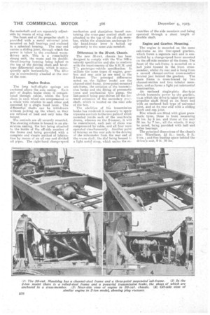
The new 30-cwt. chassis has been designed to comply with the War Office subsidy specification and also to conform with the requirements of the S.M.M. and T. 'a paesenger-vehicle specification. It utilizes the same types of engine, gearbox and rear axle as are used in the 2-tonner. The principal differences noted on the lighter model are the channel-steel frame, three-point-mounted sub-frame, the omission of the transmission brake and the fitting of pneumatic tyres and mechanical tyre pump, the last-named being gear-driven off the for-: ward extension of the secondary pei.'°shaft:, which is located on the near side of the box.
The abolition of the transmission brake has rendered it necessary to apply separate controls to the two pairs of shoes mounted inside each of the rear-brake drums, whereas on the 2-tonner,, it will be remembered, each pair of shoes was Compensated by cable, and all four were operated simultaneously.Another point of interest on the tear axle is the driving of the mileometer from the rear end of the worm shalt. the dial being housed lit a light metal strap, which unites the ex
tremities of the side members and being operated through a short length of flexible shaft.
Engine and Gearbox Mounting.
Theengine is mounted on the saute sub-frame as the four-speed gearbox, which forms a separate unit and is controlled by a change-epeed lever mounted on the off-side member of the frame. The front Of the sub-frame is mounted on a ball joint, housed in the front crossmember, whilst its rear end is hung from a second channel-section cross-member located just behind the gearbox. The main frame is cross-braced by two channel-section and two tubular members, and so forms a light yet substantial construction.
An enclosed single-plate disc-type cloteh transmits power to the gearbox, tam which the drive is taken by an open propeller shaft fitted at its front end with an enclosed ball type of universal joint, and at its rear end with a sliding block and cup. joint. • , Disc wheels are fitted with giant pneumatic tyres, those in front measuring 36 ins. by 6 ins, and those at the rear 38 ins. by 7 ins., all the wheels, it may be noted, being provided with balland
roller bearings. ,
The principal dimensions of the chassis are: Wheelbase, 12 ft. ; track, 5ft. 9 ins. ; and-free loading apace behind the driver's seat, 9 ft. 10 ins.