


MODERN ME7 S OF TIPPING.
Page 16
Page 17
Page 18
If you've noticed an error in this article please click here to report it so we can fix it.
SOME YEARS ago there was a regular flood of tipping gears of all types, some almost impracticable in their design. The unsatisfactory creations of inventive minds have met the fate which was ordained for them, and have passed from the sphere of useful activity. A few are still to be found on ancient and decrepit vehicles, but, in the majority of cases, they have either been scrapped or replaced by more modern types. Consequently the number of tipping gears on the market has considerably decreased, but those surviving are all of proved • reliability and can be looked to as a means for expediting the unloading of vehicles and to have a life which may easily exceed that of the vehicles upon . which they are mounted. This is all to the good, and is merely another instance of the survival of the fittest.
Ample Choice of Gears.
There is still sufficient choice to satisfy the most exacting, from the simple hand-operated single-screw gear to the still simple, but enormously powerful, twin-ram hydraulic type' such as that employed in conjunction with bodies built to carry 12-ton loads. Tipping gears must of necessity conform to a certain extent with the types of vehicle to which they are fitted. In some vehicles it has proved a very simple matter to make use of the source of power by which the vehicle is driven ; for instance, in the team wagon steam may be employed to drive either a separate pump or injector. In the electrical vehicle power may be taken from the accumulators and used in conjunction with a separate electric motor of small h.p., whilst in the petrol vehicle a power take-off can be fitted to the gearbox, or other arrangements made to operate the gear direct. In the case of hydraulic gears, the pump acts as an intermediary, but this may be driven from the gearbox or by chain from the clutch shaft. Use has also been made of clutches or of friction wheels pressing against the periphery of the flywheel. This method of driving is also applied in the case of certain makes of steam wagon.
In considering the total number of power-operated gears which are available, we find that there is a big preponderance on the side of the hydraulic ram in one form or another.
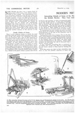
Dealing first with steam wagons, there is the Sen. tine!, which embodies a single, fixed, vertical cylinder of large bore, with a connecting rod flexibly fastened to the piston of the hydraulic cylinder at one end and to the tipping body at the other, the body being suitably strengthened for the purpose. Water under pressure for operating the 'ram is obtained from a special injector pump.
A _gear somewhat resembling this is employed on the Foden, but, in this case, there is a special pump for the water, similar to that used for feeding the boiler.
Both these gears are ideal in their simplicity, and there is only one possible objection to them, and
that is the boiler must be under steam pressure before tipping can be effected, for a situation is conceivable in which_ a vehicle may have to remain loaded for some considerable time before its contents are tipped into a barge, in which ease it would have to be under steam, or if the waiting period were too long, steam would have to be raised before tipping could be effected ; but such a situation occurs so seldom that it may well be neglected in view of the other advantages.
Another simple gear is that employed on the Tasker wagon. In this case it is purely mechanical, a friction wheel being brought into contact with the flywheel by means of a long screw and handwheeI, operated from the driver's cab. A chain from this friction wheel connects it to a short shaft passing through the off-side side member ; thence a second chain is carried inside the girder to a pair of spur gears operating a cross-shaft which carries a set of bevel gears driving the single screw behind the cab. The advantage of this gear is that it can also be operated by hand, so that the engine need not necessarily be working.
The gear used on the Clayton steam wagon is somewhat unusual. It consists of a. neat turbine steam engine attached to the chassis frame, and with a spur reduction gear between it and the cross-shaft carrying the bevel gears for rotating two screws fitted between the cab and the body. It is extremely • simple and is operated by one small lever, and can be applied to either end-tipping or side-tipping bodies. A feature of this gear is the total absence of high-pressure packing leathers and a general freedom from leakage.
In the Yorkshire steam wagon the body is forced backwards on runners through the medium of links attached to a nut running. on a horizontal screw. Vvien the body reaches the tipping position the small wheels at the forward end run up short ramps, whilst hooks on the .body frame Come into contact with rollers attached to the upper web of the chassis frame side members, and the body is then tipped over by the continued movement of the nut. This gear also can be operated by hand or mechanically, the power drive being effected by a steel cone clutch engaging with a cone in the pump spur wheel.
Hydraulic Types Popular.
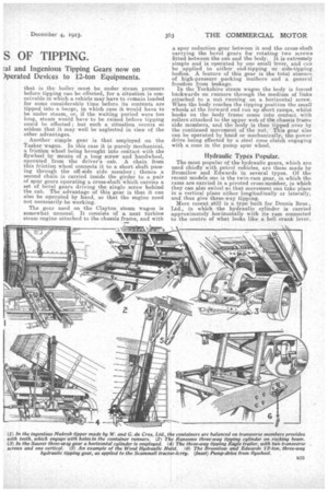
The most popular of the hydraulic gears, which are used chiefly with petrol vehicles, are those made by Bromilow and Edwards in several types. Of the recent models one is the twin-ram gear, in which the rams are carried in a. pivoted cross-meinber, in which they can also swivel so that movement can take place in a vertical plane either longitudinally or laterally, and thus give three-way tipping.
More recent still is a type built for Dennis Bros., Ltd., in which .the hydraulic cylinder is carried approximately horizontally with its ram connected to the centre of what looks like a bell crank lever. but which, in this case, is fulcrumed below the level of the chassis frame and with its uppers portion provided with rollers running in steel channels carried on the underside of the body, the last-named being pivoted at the rear in the usual manner. The interposing of this special lever between the ram and the body causes a gearing-up effect, but it is important to note that as the effort takes place first towards the front of the bod_y and is gradually moved towards the rear as the body lifts, the gearing-up gradually increased, and thus it does not throw excessive stresses on the mechanism.
High-tipping Obtained.
This type of gear gives a very high angle of lift ; in fact, so much so, in the case of the Dennis, that a recoil spring has to be fitted between the ram and the front of the cylinder to •return the body, which actually passes the balancing point. Such a high angle of tip is not often required except in certain work, such as transport in connection with tanneries. The ordinary type of tipping gear gives an angle of between '40 and 50 degrees, and suffices for most purposes.
The same makers market a telescopic hydraulic gear in which the cylinders are fitted between the cab and the body. This is used on the Karrier lowloading refuse-collecting vehicle, and is not primarily intended for very heavy work.
The Wood Hydraulic Hoist is made by the Hydraulic Hoist Co.' of Lord Street, Southport, in two types. One model consists of a large single cylinder fitted between the cab and the body, and in which is a T-headed ram carrying two pulleys, over which
are passed wire ropes fastened to the base of the cylint er at one side and to extension brackets on the .front of the body at the other, so that, as the ram rises, the body is lifted twice the distance moved by the ram.
The second type is the horizontal form, which is applied to end tipping only. The cylinder is fixed, and the ram is provided with two larger rollers engaging with curved ramps attached to the body. tikt the sides of the larger rollers are smaller ones, Asthieli rest on plates attached to the chassis, the body being hinged in the usual manner at the rear and below the level of the chassis frame. The action of the ram is practically that of a wedge, and as it is forced out the ramps cause the body to lift to as considerable angle.
It will be noted that this does away with the need for the wire ropes employed in the previous model, and also does not detract from the loading space, as happens when the ram is fitted between the cab and body.
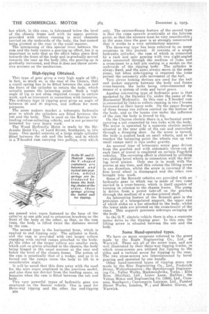
Two very powerful types of hydraulic gear are employed on the Saurer vehicle. One is used for three-way tipping and the other for end-tipping E34 only. The extraordinary feature of the second type is that the rams operate practically at the fulcrum point, so that the stresses must be very considerable ; at the same time the gear is so strongly constructed that it works in a very satisfactory• manner.
The three-way type has been referred to on many occasions in this journal. It consists of a single hydraulic cylinder, the ram of which is connected by a rack and spur gearingwith two right-angled arms connected through the medium of links and a cross-beam to a ball pin resting in -a socket on the underside of the tipping body. The cylinder is always fixed, and the arms always move in the same plane, but when side-tipping is required the links permit the necessafy. side movement of the ball.
Very clever locking devices are used for the ball and socket supports' between the body and frame cross-bearers, the locks being interecinnected by means of a system of reds and bevel gears.
Another interesting type of hydraulic gear is that marketed by the Daimler Co. under the name of the Horizontal Hydraulic. In this ease a T-headed ram is connected by links to rollers running in two I beams fulcrtnned at their lover ends. On the upper flanges of these beams run rollers carried on the bottom of the body, and as the beams rise under the influence of the ram the body is forced to tip. On the Clayton electric there is a horizontal screw carrying a nut connected by two links with the body. The screw is operated by a separate electric motor situated at the near side of the cab and controlled through a dropping door. As the screw is turned, the body is -pushed back on small wheels, and as it reaches the balancing point the wheels run up two small raniPs until it tips under gravity.
An unusual type of telescopic screw gear driven from the gearbox and with automatic throw-out at each limit of travel is employed on certain Pagefield vehicles. The reversing effect is obtained by utilizing two sliding bevel wheels in connection with the driving bevel pinion. Only one is in mesh with the pinion at any time, and this rotates the lifting screw in one direction, whilst the screw is reversedif the first bevel wheel is disengaged and the other onebrought into mesh. Some of the Renault vehicles are provided with an hydraulic gear in which use is made of two rams carried in a cross-bearer' which is itself capable of turning in relatical 'to the chassis frame. The pump is driven from a power take-off on the gearbox through the medium of a cardan-jointed shaft.
An interesting feature of the Renault gear is the provision of a triangulated support, the upper end of which slides on a bar attached to the body, whilst the lower ends are pivoted on the cross-bearer of the rams. This support prevents sideways swinging of the body. In the G.V. electric vehicle there is also a separate motor drive to the tipping gear. In this ease the lifting screw is situated between the cab and the body.
Some Hand,operated types.
We have on many occasions referred to the gears made by the Eagle Engineering Co., Ltd., of Warwick. These are all of the screw type, and are well illustrated by their three-way tipping trailer, in which cross-screws are utilized for tipping to the sides and a vertical screw for tipping to the rear. The two cross-screws are interconnected by bevel gearing and operated by one handle. Other hand-operated types of tipping gears are made by the Star Engineering Co., Ltd., Frederierk Street, Wolverhampton • the Spenborough Engineer
ing Valley Works, ileckmondwike, Yorks. ; Ellis Bros. Co.,-ialifax), Ltd., Lister Lane, Halifax ; the Vulcan Motor and Engineering Co. (1906), Ltd., CrosBens, Southport ; Carrosserie Latymer, Ltd. Pamber Street Works, London, W. ; and Messrs. Ltd., of
Warwick.