


Auto-Advance Coupling for Injection Pumps
Page 36
If you've noticed an error in this article please click here to report it so we can fix it.
A Resume of Patent Specifications That Have Recently Been Published
A N automatic advance-and-retard coupling intended for driving an iniecticm pump is shown in patent No. 561,811, by C.A.V., Ltd., and W. Nicolls, both of Warple Way, London, W.9, The two members of the coupling are connected by trapped fluids, and by increasing or decreasing the quantity thereof the required angular variation is obtained.
The drawing shows the essential part of the device, which comprises an outer ring-member fitted with a pair of vanes (1) and an inner shaft carrying a pair of close-fitting piston-vanes (2). The spaces (3 and 4) between the two sets of vanes are filled with oil and transmit the drive. By pumping oil into one space and allowing it to escape from the other, the angular relationship between the two parts can be set to any value within prescribed limits.
Oil under pressure is supplied from the lubricating system of the engine, and its admission is controlled by a central rotary valve (5). This valve is set for position by means of a centrifugal device responsive to engine speed.
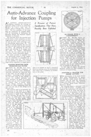
KEEPING MOISTURE FROM PRODUCER-GAS FILTER
PATENT No. 561,593, from International Harvester Company, of Australia Proprietary, Ltd., Melbourne, Australia, describes an improved form of final filter for the output of a gas producer. According to the patentee, the last filter must be fine enough to extract the smallest particles, and must, therefore, be made of i packed material such as wool or cotton-waste, as distinct from a woven fabric. Packed fillings, however, are easily clogged by water coadensing from the gas, and the aim of the design is to prevent this.
The method used is to maintain the temperature of the filter to a degree high enough to keep the moisture from condensing to liquid form. Referring to the drawing, the gas inlet (1) discharges, via radial ports, into a space
(2) between two filter packs. Some of the gas flows through pack 3, thence through a filter disc (4) to reach the outlet (5).0,
Some of the gas passes through pack 6 and travels to the filter disc
(4), via a surrounding annular space (7). The
inner unit is thus pro tected from atmospheric cooling by the layer of hot gas between it and the outer casing. Condensation is permitted to iccur in space 8, but the excess area of the '.' security " filter (4) allows free passage to the gas although water may be present. In 'fact: the water which drains down filter 4 is claimed to have a beneficial effect in washing away the accumulated dust which has a tendency to accumulate at this point.
AN ENGINE WITH A, Z-CRANKSHAFT " D A.TENT No, 561,791 shows an 1 engine employing a Z-shaped crankshaft and comes from R. Watts., 39, Tin well Road, Stamford, and others. The patentees, whilst describing the construction, make no statements in respect of the advantages thereof.
A pair of cylinders have their pistons fitted with a projecting tail which carries an offset gudgeon pin (1) embraced by a boss on a-sleeve (2). This sleeve is joumallecl on a stub (3) which is provided with a semi-circular groove around which the gudgeon pin travels. The stub (3) is attached to a long sleeve, which is journalled on the crankpin. The crankshaft has to be made in two parts to permit assembly; they fit one within the other and are pinned at the end (4).
In this type ,of engine the pistons partially revolve in their cylinders in addition to reciprocating.
ADAPTING A TRACTOR FOR HEDGE CUTTING
THE universality of the farm tractor is again demonstrated in patent No. 561,490, which shows how this machine can be used for trimming hedges and small trees. The patentee is J. Wooster, Home Farm, Thornton, Bletchley, Bucks.
The drawing shows a pictorial vietv of the outfit in action. A girder frame supports the cutter-head (1) which can extend up to 6 ft. from the track in order to work, if necessary,' on the far side of a ditch. The cutter arm can be raised or lowered about a pivot, and is counterbalanced by weights (2) con nected by a cable. A capstan (3) enables the driver to adjust the depth of cut while running. The off-Side pivot of the cutter arm can also be adjusted for Reight 'by means of a second cable worked by a handle (4).
The cutter is driven by an interior shaft which carries a pulley (not shown) on the off side, This pulley is driven by a belt from the Power take-off of the tractor. The cutter head (1) is fitted with a. bevel drive which enables it to he set in any direction. Another head can be fitted for thinning down the sides of the hedge.