


A Pilot Injection Fuel Pump
Page 46
If you've noticed an error in this article please click here to report it so we can fix it.
A Resume of Recently Published Patent Specifications Obtainable from the Patent Office,Pricel s. each.
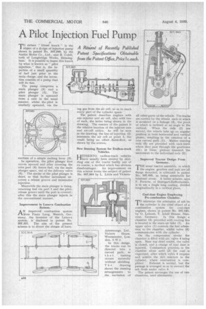
TO reduce " Diesel knock ' is the object of a design of injection pump shown in patent No. 507,940, by the Austin Motor Co., Ltd., and R. Colell, both of Longbridge Works, Birmingham. It is possible to lessen this knock by what is known as " pilot injection," that is, the injection of a small quantity of fuel just prior to the main charge, and the invention consists of a pump that will do this.
The pump comprises a main plunger (5) and a pilot plunger (2). The main plunger is operated from a cam in the usual manner, whilst the pilot is similarly operated, via the medium of a simple rocking lever (3).
In operation, the pilot plunger first moves upward and after covering the inlet port (4) forces fuel, via the main plunger space, out of the delivery valve (6). The stroke of the pilot plunger is short, so that further movement un covers a release groove and terminates injection.
Meanwhile the main plunger is rising, returning fuel via port 1 and the pilotrelease groovs until the port is covered ; after this the main plunger injects in the conventional manner.
Improvement in Lanova Combustion System.
ANfrom . improved combustion system Pr Franz Lang, Munich, Germany, the inventor of the Lanova system, is disclosed in patent No. 507,831. The aim of the present scheme is to divert the stream of burn
ing gas from the air cell, so as to reach every part of the cylinder space.
The patent describes engines with one injector and air cell, also with two of each, the latter being shown in the drawing. The essence of the patent is the relative location of the injector axis and air-cell orifice. As will be seen in the drawing, the line of injection (2) intersects the air cell at point 1, the result being an offset . flame-flow, as shown by the arrows.
New Steering System for Endless-track Vehicles.
HITHERTO, endless-track vehicles have usually been steered by skidding one of the tracks bodily out of its course, a method which has obvious disadvantages. An improvement on this scheme forms the subject of patent No. 507,964 by L. Little and Vickers
Armstrongs, Ltd., Vickers House, Westminster, London, S.W. I .
In this design, the tracks can be directed into a curved path, so that turning occurs naturally without skidding.
T h e drawing shows the steering arrangements to the exclusion of all other parts of the vehicle. The tracks are carried by the wheels each of which is mounted on a linkage (4), the pivot of which is inclined at an angle to the vertical. When the rods (2) are moved, the wheels take up an angular position in both horizontal and vertical planes, resulting in the creation of a true curved path (1). Master steering rods (5) are provided with rack-teeth where they pass through the gearboxes (3) ; in these, pinions transmit the movement to the individual rods (2).
Improved Tractor Design From Germany.
,THE usual tractor assembly, in which 1 the engine, gearbox and axle are all flange mounted, is criticized in patent No. 507,895, as being unsuitable for torsional stress. A better scheme, says F. Porsche, of Stuttgart-Zuffenhausen, is to use a single long casting, divided longitudinally in a vertical plane.
Coal-dust Engine Employing Pre-combustion Chamber.
minimize the admission of ash to the cylinder is the chief object of a combustion system for coal-dust engines, shown in patent No. 507,845, by 0. Lefnaer, 7, Adolf Strasse, Hanover, Germany. In this design a chamber (2) provided with cooling fins is located in the main air inlet (3). An upper valve (I) controls the fuel admission to the chamber, whilst valve (4) communicates with the cylinder. On the compression stroke the chamber is filled with air, valve 4 being open. Near top dead centre, the valve is closed; and a charge of coal dust is injected. Combustion proceeds in tha chamber alone until all the coal is vaporized, after which valve 4 reopens and admits the rich mixture to the cylinder, where combustion is com
pleted. Exhaust is normal, but the passage is arranged so as to extract the ash from under valve 4.
The patent envisages the use of two chambers, used alternately.