


A Résumé of Recently Published Patent Specifications
Page 54
If you've noticed an error in this article please click here to report it so we can fix it.
Compact Reduction Gear for Battery-electrics
AHIGH-REDUCTION gear, suitable for connecting an electric motor to a road wheel, is shown in patent No. 583,062 by A. E. and A. C. Morrison, 52, Woodhouse Road, Quorn, Leics. Although intended primarily for the drive of a batteryelectric vehicle, it is not limited to this application.
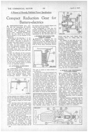
Referring to the drawing, 1 is the motor spindle and 2 the axle of the road wheel. The gear is epicyclic in principle—but rather unusual in its construction. The axle carries a sun wheel (3), whilst an outer toothed ring (4) forms the stationary member. On the motor spindle is an eccentric (5) and joumalled upon this is a ring (6) having teeth on both its inner and outer surfaces.
Under the influence of the eccentric, this ring rolls around the stator teeth, and, in so doing, imparts rotary motion to the sun wheel at a reduced rate. The amount of reduction can be as high as 100 to I. A cushion effect can be given to the transmission by mounting the stator ring on rubber, or fitting it with an hydraulic dashpat.
AN ANTI-ROLL SUSPENSION SYSTEM
A SUSPENSION system designed to prevent rolling on curves forms the subject of patent No. 582,823, which comes from L. Ballamy and R. Sheepshanks, Old Rookery House, Eyke. Woodbridge, Suffolk. Although the
scheme opposes any tendency of the tilting of the body as a whole, it does not in any way diminish the resilient action of the springs in respect of road irregularities.
The drawing shows the basic principle, although the actual construction . may differ from that shown. The wheels are each mounted on a swinging arm (I) attached to an enclosed torsion rod (2), bevel pinions on the ends of which mesh with a crown wheel (3). The shaft of the crown wheel is extended to carry brackets (4) and it is to these that the body is attached.
In action, for normal working, the crown wheel may be regarded as stationary, and the torsion rods work as they would if connected to a fixed anchorage. If, however, the body should lean over to one side, it would turn the crown wheel and load one of the torsion rods to a greater degree and ease the load on the other.
The arrangement is such that this changed loading tends to restore the body to the vertical. The scheme shown is suitable for driving axles; these are ' represented by the universal joints (5).
A RUBBER MOUNTING FOR VEHICLE BODIES
ARESILIENT mounting for the bodywork of vehicles forms the subject of patent No. 582,469, from the Andre Rubber Co., Ltd., and J. Buchan, both of Hook Rise, Tolworth, Surrey.
The unit is made to resist stresses in any direction.
The drawing shows the proposed unit in position on a vehicle in which 1 is the chassis side member, and 2 a bracket attached to the body. The unit consists of two Metal parts, that of the elmssis being constructed as a multiplicity of boxes (3), whilst the body bracket is provided with a number of tongue-like projections (4), one to each box. The intervening spaces are filled with rubber and the whole is bonded into a single component. Whether the load be applied in an up-and-down or a fore-and-aft direction, some portion of the rubber is always in compression.
RECOVERING EXHAUST ENERGY I T is well known that every internal combustion engine wastes more energy from its exhaust pipe than it delivers at the crankshaft, and many attempts have been made to eliminate, at least, some of this loss. A scheme of this nature forms the subject of patent No. 583,500, which comes from I). Napier and Son, Ltd., Acton Vale, London, W.3, A. Penn and H. Sammons.
The engine, in this case, is A two
s t r oke compression-ignition unit employing pressure charging. The exhaust manifolds (I) lead to a turbine (2), which, in this instance, is used to drive a second propeller. The exhaust turbine also drives a blower (3), which provides a first-stage compression for the air supply of the engine.
The output from this unit is fed to a second-stage compressor (4), which is mechanically driven from the crankshaft. Extra combustion chambers (5) are provided and can be brought into action by means of valves (6), if it be desired to boost the power output of the turbine. Air for these chambers comes from the second-stage compressor and fuel is delivered from jets (7). The unit shown at 8 is an intercooler for the air-supply system.
A SCHEME FOR PROCESSING CYLINDER BORES
TO lengthen the working life of engine cylinders, cylinder liners and the like, is the aim of a treatment described in patent No. 583,872, by R. Werrett and R. A. Lister and Co., Ltd., Victoria Iron Works, Dursley, Glos. The basis of the scheme is the use of chromium plating with certain modifications to assist the retention of oil.
The surface to be plated is first roughened, as by an ordinary knurling tool. After this, the knurled surface is lightly polished to remove any extrahigh spots. Next, the surface is electro-plated with chromium or other durable metal, and then given a final machining operation, such as grinding and lapping.
The last operation machines only the hills," the " valleys" being left as plated, and thus an oil-retaining surface is produced. The patent also covers the process applied to shaft and other bearings, as well as to cylinders.