


For DRIVERS, MECHANICS & FOREMEN.
Page 21
If you've noticed an error in this article please click here to report it so we can fix it.
Lamps Alight— Light your lamps at 8.8, in London, 8.58 in Edinburgh, 8.20 in Newcastle, 8:23 in Liverpool, 8.17 in Birmingham, 8.18 in Bristol, and 9.2 in Dublin.
An Expanding Cylinder Lap.
The sender of the following communteatwo, has been awarded the .10s. prize this week.
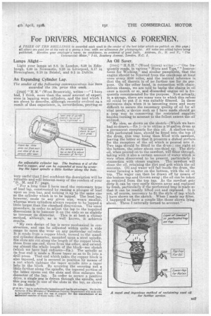
[1843] " H.M." (West Bromwich), writes :—" I have had, I think, more than the usual amount of experience in lapping worn cylinders, and the tool which I am about to describe, although recently evolved ..aa. a result of that experience, is, nevertheless,: proving se very useful that I feel confident the description will be valuable and will interest many of the readers of your 'D., M. and F.' page. "For a long time I have used the customary type of lead lap, constructed by casting a plunger of lead upon an iron bar, and turning it.up to the same size as the cylinder which is to be lapped. The lead lap, however, made to any given size, wears smaller, whereas worn cylinders always require to be lapped a little larger than the standard dimensions. The usual procedure, in order to adjust the lap to the required dimensions is to hammer it on the ends so as slightly to increase its diameter. This is at best a cluinsy method, although, as is well known, it achieves results. " My own design of lap is more mechanical hi construction, and can be adjusted within quite a wide range to meet the wear on any particular cylinder. It is made from a copper block, turned to the standard cylinder diameter, mounted upon a steel spindle. Six slots are cut along the length of the copper block, three from one end, three from the other, and extending almost the whole length of the block—see sketch (which we have had redrawn—Fn.). The spindle at its free end is made a. Morse taper so as to fit into a drill press. That end which takes the copper block is also tapered, and is secured in position by means of a nut which tightens the taper spindle into a taper hole in the block. By screwing the securing nut a little further along the spindle, the tapered portion of the latter opens out the slots and thus enlarges the diameter of the lap. In order to secure a positive drive, a single peg is driven through the spindle, and i this peg rests n one of the slots in the lap, as shown in the sketch."
H.M's." lap Is undoubtedly ingenious and has Its advantages, We doubt, however, If the Ministry of Munitions Priority Department will look with
• favourable eye upon the use of copper for the manufacture of an U nlimited number of these tools —En.]
An Oil Saver.
[1844] " H.S.H." (Wood Green) writes : —" One frequently reads, in various " Hints and Tips," " Instructions for Working," and similar pamphlets, that the engine should be removed from the crankcase at least once every 2000 miles, and the natural inference is that the oil therein is of no further use for its par-, pose. On the other hand; in connection with chain-. -driven chassis, we are told to bathe the chains in oil once a month or so, and discarded engine oil is frequently recommended for the purpose. Now actually,in a, garage, there are many uses to which this refuse. oil .could be put if it was suitably filtered. In these strenuous days when it is becoming more and snore difficult to secure the necessary quality of oil for all vital needs, a. device such as I have made should go a long way to conserving the restricted supplies besides turning to account to the fullest extent the oil' utilized. "My idea, as shown on the sketch—[Which we have had re-drawn.—En.l—is to utilize a 10-gallon drum as' a permanent receptacle for this oil. A shallow Stray. with perforated base, should be fitted into the top of the drum, this tray being then filled with sawdust, leaving the latter so that it presents a dished surface for the reception of the oil which is poured into it. Two taps should be fitted to the drum ; one right at the bottom, the other about one-third up. The dirty oil, when poured on to the sawdust, will filter through, taking with it also a certain amount of water which is very often :discovered to be present, particularly in connection with steam engines. The sawdust will clean the oil, retaining the dirt and grit which the oil contains. Oil and water will fall inside the drum, the water forming a layer on the bottom, with the oil on top. The water can then be drawn off by means of the bottom tap and thrown away ; the oil can be taken as required from the top tap. As the sawdust gets dirty it can be very easily thrown away and replaced by fresh, particularly if the perforated tray is made so that it can be readily lifted out and replaced. It is not, of course, necessary to fit the style of tap which I have shown on the sketch. When I made my filter, I happened to have a couple like those shown lying about. These I naturally turned to account."