


MECHANICAL PRINCIPLES.
Page 16
Page 17
If you've noticed an error in this article please click here to report it so we can fix it.
Loading and Unloading Vehicles. The Principles of the Lever.
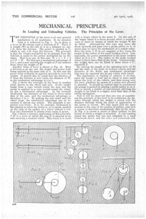
THE PRINCIPLE of the lever is of very general application in all machinery. In its simplest form it is indicated in Fig. 1. In la there is a lever (A B) resting upon a fulcrum at F. There is a weight (W) at the end of A at a distance of, say, 1 ft. from the fulcrum. The power is applied at P, which is, say, 3 ft. from the fulcrum. The principle is that the weight multiplied by its distance from the fulcrum is equal to the power multiplied by its distance. That is to say, laths case, W x1 = P x 3 or 3 P = W. We thus get a mechanical advantage of
2 to 1, and a man exerting his weight at P can balance three times his weight at W.
Another form of lever is shown iri.,Fig. 1b. Here a fulcrum is at one end, the weight and power both being applied in the same side of it. In this case the power must evidently be applied upwards to raise the weight. It should also be noted that the distance of P from the fulcrum is four times the distance of W, so the mechanical advantage is 4 to 1.
. Fig. 2 shows. the principle of the lever in another form, known as the wheel and axle. If the weight hangs from a rope wound round the axle and the power is applied to a rope wound round the wheel, we get a mechanical advantage. In the example illustrated, the diameter of the wheel is three times that of the axle, and the mechanical advantage is therefore 3 to 1. By making the axle small and the wheel large, the mechanical. advantaFe can be increased to almost any extent. The principle is employed very freely. It is, for example, illustrated in
i
the capstan n which the power is, so to speak, applied at the ends of the spokes of a wheel without a rim. It is also illustrated in almost every train of gears. Fig. 2 shows a common application of this principle. CII is a lever of which the end D is secured to an axle carrying a toothed wheel. This wheel is in mesh
with a larger wheel at the point B. On the axle of the larger wheel is a drum around which is wound a rope • or chain by means of which the weight W. can
be lifted. Alternatively this rope may leave the drum upwards and pass over a guide pulley at A, in which case we have the mechanism of a simple crane. New the lever C D in our example is five times the length of the radius of the small toothed wheel. Consequently, the power transmitted to the large toothed wheel at B. is 5 P. The radius of the large toothed wheel is three times that of the drum. Consequently, the weight that can be lifted is three times 5 .P ; equalsan P.
By varying the length of the operating lever (C D) and the radii of the pairs of toothed wheels and the diameter of the drum, any mechanical advantage that may be required can be got within wide limits.
The application to loading of vehicles is obvious, since the weight or load can be •lifted to some point above the level of the vehicle, and then swung over the lorry platform by means of a crane and allowed to descend. It should be noticed that no mechanical advantage is gained by placing a guide pulley as at A. This is merely a matter of convenience, allowing the weight to be lifted to a higher level than that of the lifting mechanism. Now it will be observed that one way of considering the principle of the lever is by comparing the distance throughwhich the weight is raised with the distance through which the point of application of the power is moved. We may apply just the same process in the case of the system of pulleys, and such a system is therefore mechanically akin to the lever. In Fig. 4 is shown a series of three pulleys, to the lowest of which a weight is attached. A rope passing round the pulley has one end attached to a. rigid framework above, and the other end connected with the axle of the next pulley. The power may be applied upwards as at or, for convenience, a guide pulley may be added as shown by dotted lines so that the power can be applied downward as at P 1. The guide pulley ,makes no difference to the mechanical advantage obtained. Now if we pull the rope at P, a distance of 8 ins., we shall shorten the rope on each side of the pulley (A) to the extent of 4 ins. The pulley (A) will rise by this amount. The rope 2 will be shortened by 4 ins., or 2 ins, on either side of,the pulley (B). Siinilarly, the next rope will be shortened by '1 in. on each side of the pulley (0). The weight will therefore be raised 1 in. while the pull is exerted through 8 Ms., and the mechanical advantage is 8 to 1, W being equal to 8 P.
Another way of looking at the same system is that the pull (P) creates a tension in the rope equal to P. We thus have a pull equal to P on either side of the pulley (A), or a total pull of 2 P. Similarly, below B we have a total pull of 4 P, and below C a total pull of 8 P. With the addition of every pulley the pull is doubled, so that if enough pulleys are added a fairly large weight"ean be lifted by means of a small power. The system is, however, cumbrous, and can only be used for lifting weights through short dis tances. Consequently, the system illustrated in Fig. 5 is more commonly used. "Here, a rope is wound
roused two sets of pulleys. The pull (P) creates a tension in the rope equal to P. Consequently, the total pull to lift the weight is equal to P multiplied by the number of ropes leading to or from the bottom pulley block. In the example illustrated the weight that can be lifted is 4 P. This is the simplest form of pulley gear, and the one which is most commonly used.
In Fig. 6 is shown what is called a differential pulley gear, which could probably be applied to load-mg with advantage in some instances. Suppose, for example, that a detachable body is loaded on ground revel and has then to be raised so that-the lorry can run underneath it, and the body can be. secured in position. This can be effected without difficulty by a double system of differential pulleys. The prinelpre is as follows :—The upper part of the system consists of two pulleys in one, but being of slightly different sizes.The larger has a radius (R) and the smaller a radius (8). The axle bearing of these two pulleys is connected to a rigid overhead framework. One rope is wound round these pulleys and the snatchblock (B), and also round the drum (A), to which the power is applied as in a Capstan or windlass. While the drum (A) makes one revolution, the upper pulleys also make one revolution. The rope is wound on to the larger pulley and off the smaller one. The consequence is that the rope round the snatch-block (B) is shortened by an amount which is equalto the difference between the circumferences of the two upper pulleys, and the weight is lifted by half that amount.
If R and S are made very nearly equal, a, complete revolution of the drum (A) will only result in lifting the weight through a very, short distance. Consequently, an immense mechanical advantage can be obtained. Another point to which we can at present only refer in passing is that the friction of the rope wound round these pulleys is so considerable that, when the weight has been lifted, it will not rim down' again if the power ceases to be exerted, but will remain suspended without the assistance of any form of ratchet. This is, in a way, convenient, but, of cOurse, means a considerable loss of power. However, the differential pulley gear enables us to deal with very great weights even though the power at our disposal is quite small, and as such it may have useful application to the problem under consideration.
It remains to consider certain points connected with the effects of.friction upon our calculations and the means by which we can utilize, in loading. and unloading, not merely one of the principles explained, but combinations of all of them. In this particular problem it is mainly in conjunction with other principles that the principle of the lever is of practical interest.