


Simplifying Disc Brake Design
Page 70
If you've noticed an error in this article please click here to report it so we can fix it.
ALTHOUGH disc brakes are more
effective than those of the drum type, their higher cost has reacted against their more general adoption for road vehicles. An attempt to remedy this is described in patent No. 712,534, which comes from H. Butler and Dunlop Rubber Co., Ltd., 1 Albany Street, London, N.W.1.
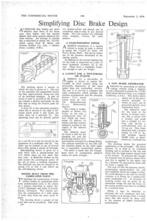
The drawlng shows a section in which the disc is shown at I. The rest of the assembly lies tangentially across the disc, approximately along one side of an inscribed hexagon. A pair of levers (2 and 3), pivoted at the bottom, . can execute a pincers movement on the disc and so bring the friction pads (4) into action.
A lever (5) is the operating member; when this is moved to the right it fulcrums about point 6 and works the other shoe via a pull-bolt (7). The operating lever can be directly pulled by a rod (8) or it can be moved by the expansion of a hydraulic unit (9). The latter can be located in one of several bores (10), giving a choice of leverage.
Self-adjusting action is given by a stud fitted with a spring-turned nut (11) which takes up any slack that may arise. A Belleville washer on the stud arrests the screwing-up action of the nut to leave a working clearance. The pull-bolt can also be turned by its spring (12) so that it can follow up the self-adjusting action.
BODIES BUILT FROM PREFABRICATED PARTS 'TO facilitate the construction of large vehicle 'bodies by assembling them from prefabricated units is the object of a scheme described in patent No. 712,917 (Henschel and Sohn G.m.b.H., Kassel, Germany). The scheme permits the construction of a wide range of body sizes from the same stock of parts.
The drawing shows a sample of the work that can be produced. Side units A36 (1), double-walled and glazed, can be assembled edge-to-edge to any desired length. The end member (2), although more complex, follows the same pattern.
A LOAD-WEIGHING TIPPER
.1-1 A SIMPLE attachment to a tipping
vehicle to weigh its toad, is shown in patent No. 712,659 (F. Tutty, 199 Priory Road, Hull). The device makes use of the pressure developed in the tipping system.
In addition to the normal tipping ram (1) the body is supported on a pair of short hydraulic cylinders (2) at the rear. These have a negligible stroke, just enough to take the weight.
A LAYOUT FOR A TWO-STROKE OIL ENGINE
A DESIGN for a two-stroke oil rA engine is shown in patent No. 712,848, its chief feature being the favourable disposition of the parts rather than any mechanical novelty. The aim is to provide a compact and rigid construction which includes the cooling arrangements and the charging blower. T h e patent tomes from H. List,
126 Heinrichstrasse, Graz (Steiermark), Austria.
The casing is wedgeshaped as shown and forms, on one side, a cooling-water duct (1) into which the waterpump (2) delivers its output and thus ensures adequate cooling in the region of the exhaust ducts (3).
The opposite space (4) forms a belt for the charging air, and the Roots-type blower (5) is conveniently attached by a flange fitting. The exhaust manifold on one side and the injection pump on the other make for a reasonably symmetrical outline.
The claim is made that the triangulated form of construction adopted makes for great strength.
A NEW SPARK GENERATOR A MEANS for generating an ignitiot voltage without using a magnet( or coil is disclosed in patent No. 712,80: (McCulloch Motors Corp., Los Angeles California, U-S.A.). The device showr makes use of the piezoelectric principle by which an e.m.f. can be generated directly from mechanical force.
The substance used for the basis of the device is barium titanate; this is mixed with a ceramic and made into a cylinder 4.2 cm. long and having a cross-sectional area of 1.6 sq. cm. This, when impacted with a kinetic energy of 1.25 in. lb., will produce nearly 10,000 volts, as determined by a cathode-ray oscilloscope.
The drawing shows the practical application of the principle. The piezo element (1) is held in an insulated housing and is earthed at the top and fitted with the high-tension output lead at the bottom. To generate the voltage, the element must be given a sharp blow and this is applied to the upper end by a hammer (2) operated by push-rods (3) from a tappet (4).
The cam (5) lifts the hammer slowly, compressing spring-washers (6), and then suddenly allows the tappet to drop. To avoid damage to the cam by reverse rotation, it is driven by a ratchet-andpawl mechanism (7). A variation of working stroke can be given by an adjustable wedge (8) and the force on the spring washers can also be modified by a screwed stud.
Whilst it may be desirable to eliminate the coil, condenser and contact breaker as at present used, it would seem that this would be done only at the expense of added mechanical complication.