


Gear-change Lever on the Steering Column
Page 36
If you've noticed an error in this article please click here to report it so we can fix it.
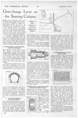
FROM Ford Motor Co., Ltd., 88, Regent Street; London, W.1, comes, in patent No. 554,587, a design for a gear-change control in which the operating lever is situated on . the steering column, just below the wheel.
The drawing shows the general la:yout, in which the gear-change shaft (1) is seen lying alongside the column. The lever itself is not shown, being .obscured by the column, but it projects on the far side at about the point 2.
The gearbox controls are cons1ructed on standard principles, but an ingenious mechanism is fitted on the column, by which the usual Z-shaped lever motion between first and second gear is avoided. The system permits a simple straight-through movement of the lever between all the gear positions.
CHAINS USED AS DETACHABLE TRACTOR STRAKES I N patent No. 554,577, taken out by J. Heiman, Auchinleck Farm, Bishopbriggs, Glasgow, the patentee contends that, although there are many designs of detachable tractor strake, it is a laborious job to fit and remove most of them, whilst some of those having retracting mechanism frequently fail " owing to wear and tear. The present idea seeks to overcome these features.
This inventor -proposes to use a nonskid chain, comprising a pair of side chains (2) interconnected at intervals by cross chains (1), which act as the . gripping member. Two turnbuckles on the side chains perniit the arcl,e to be opened for attachment or • removal. The Chain can be laid on the ground and the. tractor run on to it, a more simple operation than the bolting on of
each strake individually. Moreover; the chains are sufficiently compact to be carried on the tractor when not in use.
' A "ONE-ENGAGEMENT"
STARTER PINION
A STARTER pinion which will maintain its mesh until the engine has properly started, that is, one which is not thrown out by weak explosions and false starts; is shown in patent No. 553,611, by Bendix Aviation Corporation, South Bend, Indiana, U.S.A. The drawing shows a pinion mechanism in which the drive to the screw-sleeve
(6) is transmitted via a self-tightening clutch incorporating a rubber buffer' (1). When the sleeve is accelerated, it slides the casing (4) and its pinion. into mesh with the flywheel, in the usual manner.
The maintenance of mesh is brought about by a number of centrifugally operated catches (2) which are housed in holes in the casing. They are held inwardly by a spring Ting (5) and, during the movement of the casing (4), their bevelled ends slide over the stop. nut 3, and click into a locked position with the pinion in mesh. The strength of the ring (5) is such that an isolated firing stroke will not rotate the pinion fast enough to throw the catches out centrifugally, but this would occur during the higher rotation caused by a genuine start. The self-tightening clutch becomes free, however, during any overdrive, so that the starter motor is not driven, even by false starts.
Other modifications to starter-pinion mechanisms are shown in additional patents, Nos. 553,557 and 553,612, by the same concern.
ELIMINATING . BACKLASH FROM . INJECTION-PUMP RACKS
T'presence of backlash will reduce the accuracy of any mechanism which has to work in both directions, the control rack and pinions of an injection pump being a typical example.
TO eliminate all 553,412 slack, in thi s special case, is the object of a scheme shOwn in patent RTo. 553,412, by Automotive Products Co., Ltd., Tachbrook Road, Leamington Spa, a d G. Trapp.
The drawing shows two adja
cent pump plungers with their associated pinions and 'common rack. The invention consists of the use of a stretched spring (1) wound around and secured to a plain cylindrical part of the pinion. This results in local loading of the teeth, which urges the two pinions in opposite directions and results in a complete absorption of any slack between the pinions and rack bar. The scheme is, "of course, effective only if the load does not exceed that of the initial spring tension.
A HOMOGENEOUSLY FACED BRAKE SHOE
A DVANTAGE is taken of the latest CA manufacturing methods in the making of brake facing material by General Motors Corporation, Detroit, Mich., U.S.A., the process being covered in patent No. 554,540. The object is to produce a friction surface which is homogeneously bonded to its steel back, thus avoiding the need for rivets and the use of a thinner facing.
The drawing shows a highly magni
fied section of the proposed construction. The steel backing plate (8) is first covered with a layer of powdered alloy (cupro-nickel, for example) and this is fixed or sintered at a high temperature. The result-is a layer of metal (2) on the steel backing, this being solidly united but of porous texture. The final layer (1) consists of friction material such as asbestos, mixed with' a synthetic resin. The application of this, under heat and pressure, causes the asbestos and its bond to permeate the pores of the sintered layer and so form a lining of homogeneous texture.
As an alternative bonding material, an oxydizable oil may be used, instead of the synthetic resin, and the frictional characteristics may be modified by the addition of bitumen.