


Patents Completed.
Page 18
If you've noticed an error in this article please click here to report it so we can fix it.
N-SICID D14:. VIC E.—Morgati.—Ko. 21,635, dated 30th September, 1907.—The device comprises a small wheel (a) carried by a fork (b) mounted in a head (0) so as to be free to turn therein. The head (IA) is loosely mounted on the axle (d) of the vehicle so that the wheel (a) may trail on the ground. The wheel is provided with two corrugated rings (i) at either side and a rubber tyre in the centre. Normally the side rings (4...are out of contact with the ground, but tIpon 'lateral movement of the vehicle, the wheel (a) turns slightly which causes one of the rings (i) to be brought into contact with the ground thereby preventing fur ther lateral movement of the vehicle. Springs (g) are provided and these are connected at one end to the fork (1) and at the other end to a .second fork (e) so that they tend to force the wheel (a) on to t he ground and at the same time serve to return it to its normal position. The turning movement of the wheel is limited by a bar (h) rigidly connected to the fork (b) and arranged to come in contact with the head (b1) when the wheel has turned to its full extent.
ELECTRIC POWER TRANSMISSION. — Porsche. -No. 7,006, dated March 30th, 1908.—Mounted on the driving shaft (W) is a dynamo armature (Ad), it is free to rotate but cannot slide endwise and it is connected to the shaft by a spiral spring (F). Also mounted on the shaft (W) is a sleeve (C) which is free to slide but not to rotate. This sleeve terminates in the form of a nut which en gages with a screw thread cut on an extension on the hub of the dynamo armature (Ad). The field magnets (Mm) of the dynamo are directly connected to the armature (Am of the motor, both being supported by a bracket (G). This bracket is rigidly connected to the driven shaft (E) and the field magnets (Mm) are secured to the frame (D). In operation, the spring (F) transmits the power of the driving shaft (W) to the dynamo armature (Ad), and the current which is generated in the latter is conveyed to the two field magnets and into the second armature. In this way, the armature (Am) will rotate as a motor armature and its power will be transmitted by the bracket (G) to the shaft (Ed. When a heavy load is encountered, the armature (Ad) tends to lag behind the driving shaft and, in consequence, .is rotated slowly. This rotation of the armature (Ad), by means of its screw thread, causes the bracket (G) to move longitudinally, and thus the gap (d1) between the dynamo armature and the. opposite magnets will be increased, and, at the same time, the air gap (al) between the motor armature and the magnets built in the casing will be reduced.
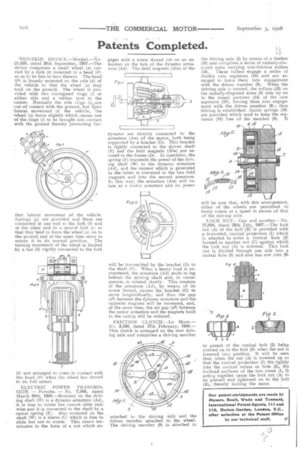
FRICTION CLUTCEL—Le Moon.— No. 3,580, dated 17th February, 1908.— This clutch is arranged on the rear driving axle and comprises a driving member attached to the driving axle and the driven member attached to the wheel. The driving member (8) is attached to
the driving axle (4) by means of a feather (18) and comprises a series of radially-disposed arms carrying anti-friction rollers (13). These rollers engage a series of double cam segments (10) and are arranged to force them into engagement with the driven member (9). When the driving axle is rotated, the rollers (13) on the radially-disposed arms (8) ride up on to the raised portions (14) of the cam segments (10), forcing them into engagement with the driven member (9) ; thus driving is established. Spiral springs (16) are provided which tend to keep the segments (10) free of the member (9). It
will be seen that, with this arrangement, either of the wheels are permitted to freely rotate at a speed in excess of that of the driving axle.
LOCK NUT.—Gay and another.—No. 17,098, dated 26th July, 1907.—The lock nut (A) of the bolt (B) is provided with a truncated, conical projection (1) which is adapted to enter a conical hole (2) formed in another nut (C) against which the lock nut (A) is screwed. This lock nut is divided through one side into a central hole (5) and also has saw cuts (61 to permit of the conical bolt (2) being pressed on to the bolt (B) when the nut is screwed into position. It will be seen that, when the nut (A) is screwed up so that the conical projection (1) fits tightly into the conic-al recess or hole (2), the inclined surfaces of the two cones (1, 2) acting together cause the lock nut (A) to be pressed and tightened on to the bolt (B), thereby locking the same.