


PATENTS SUMMARIZED.
Page 22
If you've noticed an error in this article please click here to report it so we can fix it.
• Ingenious Differential Gear.
An ingenious differential gear for an agrimotor is the subject of a patent by G. Ott, a Swiss, and it is described in specification No. 115,042. One of ourillustrations shows diagrammatically the arrangement of this device. The main driving shaft is hollow, and transverse; it drives the pinion or sunwheel of the . differential gear. The planetary pinions revolve freely upon their bearings, which are connected to one of the live axle shafts of the tractor. The external wheel of the epicyclio train is connected to the other live axle. As this arrange. ment would have the effect of driving one of the live axles in a contrary direction to the other, it will be realized that. further gearing is necessary between these axles and the actual roadwheels.
Ot ler variations of the arrangement are described, and a method of incorporating a .flexible transmission within the differential dear is also illustreteel in the specification.
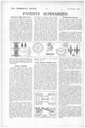
Trailer Coupling.
America's affection for the trailer, -although at the moment fairly intense, is of comparatively recent origin, ic this, country, as applied to a steam wagon, the advent. of its general use was almost coincident with the introduction of the commercial vehicle. It is therefore somewhat surprising that the following ingenious method of connecting trailer and teactor iv'hich has many advantages, has not hithirto been tried over here. It is generally agreed that in older to increase the available tractive eftbrt it is advisable to couple the tractor to the taailer by a hitch'which exerts a downward pulien the tractor. Usually this hitch or coupling is rigid in form, so that while performing the useful fiinction.eof adding to the tractive effort of the tractor when the latter is pulling, it has the disadvantage of tending to lift the rear of the tractor when the combination of Vehicles is travelling downhill and the brake is applied to the latter. The effective braking capacity i6 thdri decreased at a time when it, is most important that it should be at a maximum. '
E. O. Sutton, an American citizen, his devised, as related in No. 118,061, a dual typo of coupling. The tractive effort is imparted by a chain, a pair of chains, or other flexible equivalent, and it is usually so disposed that the point )f-,attachment to the tractor is higher than that to the trailer, the result being that when power is being exerted a downward pull is effected on the rear of the tractor. Between the two, however, a semi-rigid connention is also made. This consists of a 'knightly telescopic, ball-ended rod. The rear end is secured in a socket on thestrailer ; the fore end in a similar socket on the tractor. The rod is so disposed that it bears downwards upon the rear axle of the tractor.
When a pull is being exerted, and the chain or flexible portion of the coupling is fully extended, then the rigid rod, or strut, is also extended as regards the telescopic portion. Whenever the trailer commences to over-run the tractor, however, as, for instance, when descending a hill, or whenever' the brake is appi:ed to the wheels of the latter, this rod telescopes upon itself to a small extent, and thereafter the trailer presses upon the tractor through the medium of this rod, and exerts a force in a downward direction, thus adding to the weight of the driving wheels of the tractor and in creasing the affective and available braking capacity.
Lucas Electric .Starting Gear.
H. Lucas and others, of Joseph Lucas, Ltd., have patented in No. 118,050 an improvement in connection with electrIc starting gear. The invention relates to that type of gear in which a pinion, held upon a short, quick-threaded screw' is caused to mesh with gearing on the flywheel coincident with current being supplied to a starting motor. The object of the invention is to restrain the pillion from revolving during the time in which it is being moved longitudinally into engagement, and it is attained by utilizing some of the current provided to energize an electro-magnet, the pull of which 18 in close proximity to the teeth of the pinion, which is thus prevented from -revolving until it i6 slid along the screwed spindle and engaged. The current is then cut off from the electromagnet, and increased current supplied to the motor, and the starter operates.
. Detail Improvements.
E. M. BarloWs spring wheel (No. 118,053) embodies a. number of smallshaped flat springs, secured round the rim of the wheel, as shown in the drawing which we reproduce. There may be two or three rows of these springs aide by side, and the construction is such that a little long4udinal movement of One end of the spring is permitted under flexion.
A priming device, which is the subject of specification No 118,060, by IL D. Waterhouse, an American, is almost a miniature carburetter in itself. It is attached directly to the induction pipe between carburetter and engine, and the construction is such that by movement of a small plunger operated from the
dashboard a petrel jet is exposed at the narrowest portion of a constricted passage from the air to the induction pipe. It is contended that by this arrangement a fully vaporized rich mixture is-easily induced for starting purposes. This vaporizer is, of course, thrown out of action so soon as the engine has started and the regular carburetter conunenSes to operate.
Specification No. 11'7,968 relates to r splashguard for a motor vehicle. I semi-circular band is clipped to the roars springs by brackets which project one on each side of the wheel. Attached to the band, and descending so that it approaches to within a short distance of the ground and covers the lower half of the circumference of the wheel is a flat wing of flexible material. This completes the guard. . The patentee is A. H. R. &Indies, a Swede.
Most Dunlop tyre valves are slated in the body of the•valve so that the plug, which has corresponding projections, will not revolve when it is being screwed in place. It has been found that these slots weaken the valve considerably, and breakages are not uncommon. The present patent, No. 117,995, taken out by the Dunlosi Rubber Co., Ltd., embodies an improvement, on this construction. Instead of cutting slots in the valve, depressions are formed in the flat sides of, the body, and these project inwardly. Grooves are formed on the outside of the plug which register with these impressionstor projections so that the same object is attained.
method, of manufacturing sparking plugs is the subject of specification No. 118.012, by J. E. Barrows. The metal body of the plug and the electrode are held in a jig or mould, into which in squirted, under high pressure, insulating material. The interior of the mould is, of course, so formed that when the insulation has become set the plug i. complete.