


UPKEEP OF COMMERCIAL ELECTRIC VEHICLES.
Page 18
Page 19
If you've noticed an error in this article please click here to report it so we can fix it.
The Sixth Mick. ,
THERE ARE REALLY two forms of the alkali battery on the market, but only one, that . worked by Mr. Edison in America, and some Germans, has been adapted for vehicle driving. The special feature of the Edison battery is its great mechanical strength. One of the troubles that arose with the lead battery, in the early days and for some time after, was the low mechanical strength of the lead grids ; they are apt to fall to pieces, especially after being badly sulphated. The 'grids of modern lead batteries have been strengthened by the addition of asmall percentage of antimony as an alloy to the lead, and by other methods ; but they are still, owing to the characteristics of the metal itself, not so strong as those of the iron battery.
• In the hip battery, the active materials are nickel oxide and a special oxide of iron, and they are contained in special carriers formed of nickelled steel. It is important to notice here that the tubes forming the carriers are made of steel, plated with nickel, and not of the modern alloy, nickel-steel. The nickel • oxide plate is the positive and the iron oxide the negative. The nickel oxide is carried in small tubes arranged vertially and perforated by a large number of fine holes, the tubes being held in a. nickelled steel plate arranged for the purpose. They are pressed into spaces in the plate by hydraulic pressure. The iron oxide is carried in small rectangular boxes, also held in a nickelled-steel plate arranged for the pur pose. As in the lead battery, positives are held between negatives, the whole being immersed in a 20. per cent. solution of caustic potash, the containing vessel being also nickelled-steel. There is a cover of nickelled-steel, the terminals of the plates, which are connected together in the same manner as the lead cells, projecting through the cover. The plates are insulated from cash other, and from the containing cell, and the terminals are insulated from the cover by rubber insulation. Each cell has a valve cap designed to allow the gas to escape, when it is formed during charge ; it also allows of water, or caustic potash being introduced to make up, but it is claimed that the cap prevents the ingress of air into the cell. The plates have to be kept covered, just as with lead cells, and only distilled water and pure caustic potash must be employed in making up.
The Edison battery furnishes a pressure from 1.4 volts downwards ; and it is advisable not to discharge it below 0.9, or better, 1 volt. It requires a charging pressure of 1,8 volts per cell. It is claimed that the Edison battery does not suffer from being laid on one side, nor if it is discharged right down to zero, but, as with the lead battery, it is best to keep it charged. It is made up in a few definite sizes. It will be understoed that a larger number of Edison cells are required for any given work, to drive a given vehicle, than of lead cells.
Charging the Batteries.
As mentioned in the previous article, lead batteries require a charging pressure up to 2.76 volts per cell; alkali batteries require up to 1.8 -volts per cell, and these pressures must be availahle. As mentioned, however, only 2.2 volts per cell is usually required for a considerable portion of the charging period, and a proportionately lower pressure with the alkali battery. This means that some method of varying the pressure has to be provided.
Where the charging is done at one of the town generating stations, the engineering staff there will arrange this; they , have every apparatus that is necessary for the purpose. Where the owners of a ear, or a number of cars, prefer to charge the batteries on their own premises, there are two or three ,methods open to them to provide the necessary pressure and the necessary variation. As mentioned in the previous article, only continuous currents can be employed, and, therefore, where the town service is alternating, some apparatus has to be interposed to convert the alternating currents to continuous.
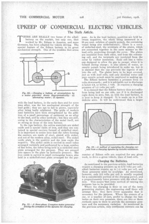
The simplest arrangement is by means of a motorgenerator. The motor is arranged to receive and use alternating currents, whatever they may be, at what ever pressure, and to furnish power for driving a continuous current generator which furnishes the required current, at the required pressure. Fig. 30 shows the arrangement diagrammatically,. and Fig. 31 is an illustration of an actual apparatus. As will be 'seen from the figure, there are two distinct machines, mounted on one bed plate, having their axles connected together mechanically. The motor generator can be arranged very conveniently for varying the pressure by inserting a variable electrical resistance in the circuit of the field magnet coils of the generator as is shown in Fig. 32.
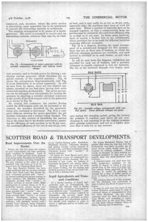
By varying this resistance, the current flowing round the field-magnet coils can be increased or decreased, the pressure furnished by the generator being also increased or decreased. Fig. 33 is a complete diggram showing the motor generator, the adjustable resistance and a battery being charged. The objection to this method,of furnishing the current lies in the losses due to the double conversion ; assuming the efficiency of each machine to be 80 per cent., the combined efficiency of the two is only 64 per cent. at best, and it may easily be as low as 50 per cent., especially after the machines have been at work for some time. Where a number of batteries have to be charged together, so that a comparatively large apJ paratus may be employed, the combined efficiency may be as high as 81 per cent. In those cases, however, there is usually a further loss at the switchboard, where provision has to be made for-different batteries requiring different pressures. Fig. 34 is a diagram showing the usual arrangement of a switchboard designed for this purpose ; there are two or three sets of busbars, at which the different charging pressures are available, and each. battery is switched on to each busbar, as and when required. As will be seen from the diagram, voltmeters are provided for each set of busbars, and a portable voltmeter is usually employed to test the batteries. The life of the batteries depends very largely upon care during the charging period, giving the battery the pressure it requires, and above all not overcharging it, not exposing it to the highest prelisure after gassing commences, and not to a higher pressure than it calls for at any moment.