


OVERHAULING THE LEYLAND.
Page 24
Page 25
Page 26
Page 27
If you've noticed an error in this article please click here to report it so we can fix it.
No. 15. Pronounced Accessibility, Stoutness of Construction, and Ease of Repair are the Leading Features of the 4 Ton Leyland Chassis.
HE GOVERNMENT 4 ton Leyland group of models, which includes the R.A.F. recondi
tioned machines, and with the overhaul of which We deal in this article, requires little or no introduction to our readers. Chassis of these types have proved their exceptional capabilities under the arduous conditions of war service and, in fact, the Leyland was adopted as standard by the R.A.F. Few repairers need fear to undertake either minor or major repairs on these chassis, as throughout their design care has been taken to ensure accessibility and to provide facilities for the taking up of wear. Some of the units have proved so reliable and are of such simple construction that there is very little to be said regarding their repau'. or overhaul, and much of this article will be devoted to appliances, such as ball race extractors, which facilitate dismantling or assist the ordinary fitting jobs which every motor vehicle requires.
Dismantling.
Starting with the complete vehicle, the first task, on commencing the overhaul, is to remove the body, which can be put aside for cleaning, repairing, and repainting. The ehassis should then be-checked over to find out if there are any missing parts, as, if this be done at once, the ordering of these parts will be expedited and delays may be avoided. In some eases, the use of a hose pipe alone will not
be sufficient to clean off the mild, and it will have to be scraped off with some sharp instrument. After this initial cleaning, the dismantling proper may commence.
Starting at the front end of the -chassis, as is the usual practice, the radiator should be removed, after disconnecting. the water. pipe connections and ,removing the holding-down caps of the trunnion brackets. The starting handle should next,receive attention. To take out the engine, loosen the clutch withdrawal a,rgll bolts and knock the arms to either side until clear. Now undo the four clutch coupling bolts and the eight boltsholding the engine bearers to the frame. After disconnecting the 'carburetter and magneto controls the engine can be lifted straight out of the chassis or slid out towards the front.
It is, not essential to remove the steering gear•for this purpose, but in the case of a complete over
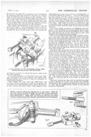
haul its removal may facilitate matters. It can be taken down by removing the steering wheel, disconnecting the steering box from the frame, and drawing it down, together viith the steering shaft, until the latter is clear of the steering pillar. To take down the gearbox, drop the front end of the torque tube by undoing the four bolts at 'the bottom of the spherical joint housing, which is carried by a cross-member immediately behind the gearbox, unscrew the six nuts holding the spherical end of the torque tube and slide this end hack along the tube. If found to be tight this operation can be facilitated by inserting two long setscrews into the two tapped holes provided for the purpose in. this member. The ends of these setscrews will bear against the flange of the torque tube and force back the spherical end. When this is done it will be found that the four nuts of the cardan shaft rear die box are exposed, and by removing these the joint can be disconnected. The actual disconnecting of the gearbox can be done in two ways. If it is required to. remove the box for repair with the 'body in, position, then it can be dropped by removing the bearer caps, but during the overhaul it is better to unbolt the bearer tubes from the side members.
It is quite possible to overhaid the rear axle without removing it from the chassis, and unless very serious repairs are required it may be advisable to follow this procedure.
After lifting the top cover the differential can be taken out by removing the side cover.plates and extracting the compensating shaft, which, floating as it does, comes out quite easily. The weight of the
differential gear and crown wheel is considerable, so it should be lifted out carefully. Once the differential has been taken out the repairer is free to test the driving shafts for wear. Jai the bearings (that is, of course, if the wheel driving dogs have been removed), and the bevel pinion shaft can be inspected at the same time. This shaft is carried on a ball race, and is provided with a thrust bearing so that the shaft should be tested both for wear on the races and for end play.
It is very. seldom necessary to withdraw the axle shafts, as the bearings are of,such ample dimensions, but if at any time it is found necessary to do so, undo the split-pinned nut at the inner end of each and .withdraw the shafts from the,eut-Side.
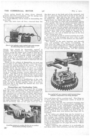
The 4 ton Leyland is provided with a double reduction rear axle, the first reduction being through bevels and the second through.spur gears. The spur wheels are carried on large ball races held in housings in the axle casingjand they drive the axle shafts through. the' medium of splines. If it is required to remove one or both of these spur wheels they can be driven out by inserting a long rod in lieu of the axle shaft 'and 'driving each wheel out by hitting the outer end of the rod. .
Sometimes the large ball race on -which each spur wheel Tuns will rensam in the. axle easing, but more often it will come out on the boss of -the wheel, and if this be the caseAit" may be found very.';difficult to remove Without causing damage. A simple. but effective extractor has been designed by the. manufa,eturers to remove this ball race. This device is built up with four clamping pieces and four blocks, each of which carries a. setscrew. When halted tightly together the inside diameter is .turned in a lathe -to a tight fit on the outer ring of the ball race, leaving .a slight lip 'at the base in order to grip under the race and to assist in preventing the latter from slipping.
To remove a rear wheel; undo the cap nut and there will be found a combined colletand driving dog held in position by a collet pin. The latter is lacked in position bylme.ans of a split pin. By extracting this and the collet pin, the. driving.clog .can be slipped off. The wheels are heavy and should preferably be lifted off with the aid of a jib crane or block and tadkle..
The front wheels are also held in position by collet washers pinned, us in the case of the rear wheels. Occasionally these collets are diffisult to. remove ; if so, they can be pulled off by means of the special extractor illustrated.
Every spring should be taken down, cleaned, greased, and reset if necessary, and the spring eyes and spring pins examined for wear.
No great difficulty will be found in dismantling the front axle.
After the units have all been removed from the chassis, they should be thoroughly washed in paraffin. The Leyland. Co., when overhauling their vehicles, steam the engine over a tank so that the oil is thinned and runs out. The engine is then dipped bodily into a tank of boiling caustic soda eolutian, after which it is washed in a tank of paraffin in order to prevent the. caustic soda from corroding the aluminium. The same procedure is followed with the other units.
Whilst on the subject of dismantling we must not fail to refer to two other ball race extractors which are used for various parts of the chassis. Of these, perhaps the. most interesting is one in which a split, tapered barrel, the two halves of which are located by pins, can be slipped, together with a taper-ended bolt, through the centre hole of a ball rice which, being in a -blind housing, cannot otherwise be extracted. The halves fif the taper barrel are provided with a slight lip, and by drawing the taper-ended bolt up between them they are forced out against the interior ring of the hall race.
The other extractor is a modification of the ordinary type, but the end which grips the bail race is made in halves bolted together when in position, each half has a, lip which fits behind the race and assists in gripping it.
Dismantling and Overhauling Units.
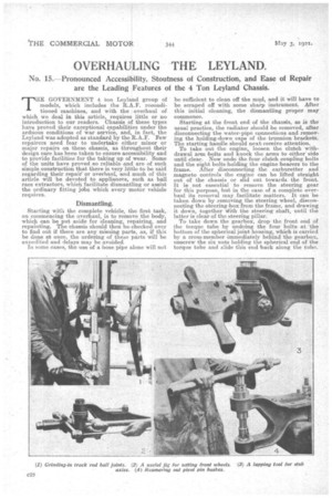
To dismantlesthe engine, first remove the oil sump, then the water -connections and exhaust manifold, take off the fan driving pulley, either by means of a claw extractor or a strap and two bolts, and remove the governor gear by unscrewing the two nuts holding this in position. The timing ease may now he taken off. Next clieconnect the connecting rods, when the .crankshaft will be ready to drop away by undoing the main bearing nuts. To extract the camshaft, if this be necessary, take out the split cotter pin from the skew gear at the back end of the camshaft, and the two setscrews which will he found at the side of the crankcase. This will free the. shaft, and it can be pulled out. The timing gears are provided with tapped holes, by which they may be withdrawn. ft it is necessary to renew the intermediate timing wheel spindle, this may be found somewhat difficult without the use of a. special extractor. The latter, in its simplest form, eonsists of a forged centre drilled through to pass over the spindle and provided with a boss in which is a setscrew, the end of which is made to fit the hole which will be found at the end of the spindle. Each side of the forging is tapped for a long setscrew, the end of which can bear on the face of the timing gear case.
The erankshaft should be tested carefully for truth. If scored, or if the journals are worn oval, it may have to be reground, or if the defects are only slight, • lapped by hand. The brasses of the main bearings and big-ends may, and probably will, require re-metalling. If much worn the edges of the brasses can .be built up With sheet copper soldered into position and filed to the correct shape and thickness. The makers employ a neat little jig for this Purpose, and this ensures that each brass w1l 'be a perfect half. This filing up is done before the white-metal centre is bored or reamered out for fitting.
It is possible that the two ..earnshaft bearings may require renewal, and it is almost always advisableto renew the bush in the intermediate timing wheel. The gudgeon-pin bushes and piston rings should he carefully examined and replaced if. necessary,. and the cylinders, if worn or scored, may have to be rebored, in which case, new pistons and rings will be necessary.
If the valves are pitted they can be turned in a, lathe, but if badly worn they should be renewed, and the sea.tings may require reeutting with the usual tool which is employed for that job, and which consists of a milling cutter' .of which the teeth are made to the correct angle of the valve seat. One of these cutters is illustrated on the page devoted to "Hints on Maintenance."
Before replacing the cylinders, it is preferable to test them under water pressure, and this also applies
to. the water pumps, after these have been repaired, rebushed if necessary, and the glands fitted with new packing.
The clutch can very easily he dismantled without the use of .any special spring releasing device. The friction material seldom requires renewing, although it may be necessary to tighten the rivets. A step sometimes develops on the material, -and if this is the case it should be hammered down. Do not rasp it down as this cuts the strands Of thematerial. The crankshaft spigot bush may require replacement.
. Two types of gearboxes are employed on the subsidy .medel. One is the 8.4, in which the gears are bolted into position, and the other the .5.5; in which the gears are on splinecl shafts. Dealing with the latter, in order to strip it remove the housing of the primary shaft and then of the rear driving shaft and pull the shaft right, through, leaving the gears loose in the box. To extract the layshaft, remove its two housings and push the end carrying the .small pinion back until the front end is free, when the shaft can be lifted out complete with its gears.
Practically nothing is required to be clone in the majority of -cases, although possibly a washer may have to be made for fitting behind the thrust on the driving shaft. It may be necessary to replace the thrust button bearing against the spigot on the driving shaft .and also those at each end of the layshaft. If the. ball race housings are worn these can either be renewed or built up by the electrical deposition of iron, which latter job must, of course, be done by a concern specializing in this process. If the faces of the selector forks are slightly worn, they can be built up by the electrical welding process. In some cases the felt waShers which prevent the leakage of oil may require replacing. After fittinga new washer it is a difficult task to replace a cap with its felt washer on to a boss, and to assist in this operatian a tapered mandrel can be employed. Such a mandrel should be made with a spigot end to fit the hole in the boss and with -a nua,ximurn diameter equal to that of the boas.
We have dealt with the way in which the rear axleis dismantled. As regards its repair, beyond the fitting of new bushes for, the differential pinions and possibly the replacement of worn bearings, little else will be required. Any end play on the axle shafts is taken up by providing bronze thrust rings of increased thickness for the rear wheel hubs. -The differential pinion pins ,sometimes scare, and must then be renewed.
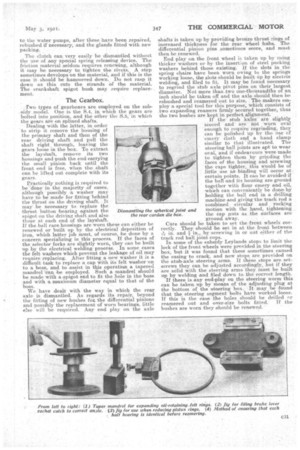
End play on the front wheel is taken up by using thicker washers or by the insertion of steel packing washers behind those existing. If the slots in the spring -chairs have been worn owing to the springs working loose, the slots should be built up by electric welding, and filed to fit. It may be found necessary to regrind the stab axle pivot pins on their largest diameter. Not more than.two one-thousandths of an inch should be taken off and the axle should then be rebushed and reamered out to size. The-makers ecaploy a special tool for this purpose; which consists of two expanding reamers firmly secured together, thus the two bashes are kept in perfect alignment. If the stub 'axles-are 'slightly
scored and are iiht Worn oval enough, to require regrinding, they can be polished up by theiise of emery cloth and a hand clamp similar te that illustrated. The steering ball joints are apt to wear oval, and if -endeavours were made to tighten them "by grinding the faces of the housing and screwing the -caps tighter, this would be of little use as -binding will occur at -certain points. It cart be avoided if the ban and its housing are ground together with flour emery and oil„ which can conveniently be done by: holding the ball end in a drilling machine -and giving the track rod a combined circular and rocking motion with the hand, tightening the cap nuts as the surfaces are ground away.
Care should be taken to set the -front wheels correctly. They should be set in -at the front between in. and 4. n., by screwing in or out either of the i track rod ball joint cups.
In some of the subsidy Leyland's stops to limit -the lock of the front wheels. were provided in the -steering box, but it was found that these sometimes caused the casing to crack, and now stops. are provided on the stub-axle 'steering arms. If these stops -are setscrews they can he adjusted accordingly, but if they are solid With the steering arms they, must be built up by welding and filed down to the correct length.
If there is any end-play on the steering worm this can be taken up by means of the adjusting plug at the bottom of the steering box. It may be found that the steering segment bolts have worked loose. If this is the case the holes should be drilled or reamered out and over-size bolts fitted. if the bashes -are worn they should be renewed.