


MAKING SOME USEFUL TOOLS.
Page 27
If you've noticed an error in this article please click here to report it so we can fix it.
Our Driver and Mechanic Readers' Suggestions for Special Tools.
MHE standard tool kit of a large num ber of lorries does not always contain just the particular item required for a job which does not frequently arise. On the other hand there are many tasks for which, if a special tool be made up, the time for a repair can be reduced, or the inconvenience lessened.
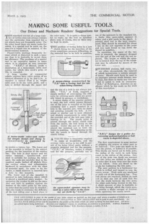
Poppet-valve seatings frequently become pitted or distorted in such a manner that it is desirable to re-cut them for efficiency. The purchase of a special tool is an expensive matter in cases where it is required at rare intervals only. " of Stroud, sends a description of a home-made valve seat cutter, for which this week's prize of 15s. is awarded.
A large number of commercial vehicle engines have valve guides of an internal diameter of Ain. and ft in. A mandrel is turned from ft in. bright mild steel to fit the valve guide, and a hole is drilled through the upper end
to receive a toromy bar. The lower end of the mandrel is drilled in the correct position for the insertion of the cutting bar. The hole is filed square and the cutter inserted. Quarter-inch tool steel is suitable for making the latter part: the ends are carefully filed to the required angle, backed off slightly from the cutting edges, and subsequently hardened in accordance with the class of material used. In order to fix the cutter, a mall setscrew is inserted into a hole in the mandrel, The lower end of the mandrel is screwed to take lock-nuts, above which is placed a machieed Vain washer. In operation the washer is slid up the mandrel and held in position against the bottom of the valve guide by the nuts, in order that the cutter may be steadied ; this also tends to overcome the difficulty of the tool riding over a hard place in
the valve seat. It is quite a cheap matter to make up the tool as specified above and, of course, two•or three may be kept in stock.
THE problem of boring holes in a new clutch lining for the insertion of the rivets sometimes presents difficulties, as the material has to be held in position, and the use of a drill is not always pos sible. " T.S.," of York, suggests a simple method of overcoming the difficulty by utilizing parts which are generally found in garages or workshops.
A screw clamp of the popular pattern is used, the bolt which passes through one of the jaws is rounded at its inner extremity and a punch inserted in a hole in the opposite jaw, with its sharp end pointing towards the bolt. A terminal or similar nut is next obtained and slightly countersunk in order that the rounded end of the bolt may take a bearing in it. The punch point is passed through the metal clutch cone from the inside, the bolt being on the outside. Under the end of the bolt is placed the terminal nut to hold the fabric in position. By tightening up the bolt the punch is forced through the clutch lining.
A VALVE lifter is frequently required in cases of breakdown, and the average valve spring is too stiff tosper:nit of its being lifted easily without a properly designed tool for the purpose. " C.C.S.," of Aberfan, makes a simple tool for the purpose, partially out of one of the spanners in the standard kit. A fairly thin open-ended spanner is taken, and a slot. made in the shank. A pointed steel rod is the next requirement. This should be screwed for about 2 ins, at the end opposite to the point and two nuts found to run down the thread in question.
In operation, the upper of the two nuts is removed, the spanner dropped over the end of the rod and the nut replaced. The height at which the spanner is located from the top of the crankcase may be adjusted by means of the lower nut.
STUBBORN pinions, ball races, etc.,
are often encountered, the removal of whieh necessitates a certain amount of force. Should such force be used in an improper manner much damage may be done, but there is rarely any tool provided to assist in such an emergency.
" of Brislington, describes an appliance which he has made up for work of this description.
The first requirement is some method of gripping the pinion or other part to be removed. Two jaws are made to fit over the pinion, or behind it if possible. Two blocks are bored out to form jaws, the radius of the curve in each being equal to the radius of the pinion. Into one of the jaws two studs are screwed and two holes are drilled in the other in order that it may drop over the studs on its fellow. Nuts are fitted on the studs for tightening the two jaws.
The next portion is a horizontal bar which is drilled and tapped to take the centre screw. Fork ends are machined at each end of the horizontal bar. Two link pieces are required, drilled at each end an that one end of each link fits over the studs between the two jaws, the other ends being riveted to the bar. A slight amount of play is desirable iii the holes through which the rivets pass. to provide a slight amoant of freedom when operating the centre screw.