


To Protect Injection Pumps Against Seizure
Page 36
If you've noticed an error in this article please click here to report it so we can fix it.
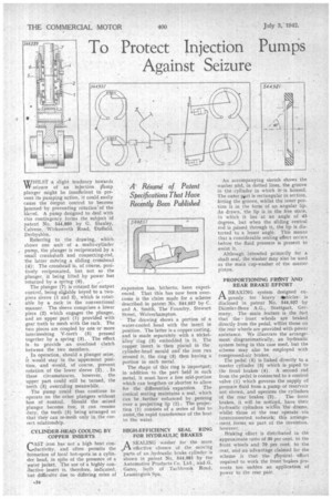
WHILST a slight tendency towards seizure of an injection rump plunger might be insufficient to prevent its pumping action, it could easily cause the output control to become jammed by preventing rotation' of the b'arrel. A pump designed to deal with this contingency forms the subject of patent No. 544,889 by G. Stanley, Calvene, Wirksworth Road, Duffield. Derbyshire.
Referring to the drawing, ' which shows one unit of a multi-cylinder pump, the plunger is reciprocated tiy a small crankshaft and connecting-rod, the latter moving a sliding crosshead (4): The crosshead is, of course, positively reciprocated, but not so the plunger, it being lifted by power but
returned by 'a spring (6). •
The plunger (7) is rotated for output control, being sligably keyed to a twopiece sleeve (1 and 2), which is rotatable by a rack in the 'conventional manner. The sleeve comprises a lower piece (2) which engages the plunger, and an upper part (1) provided with gear teeth to mesh with the rack. The two pieces are coupled by one or more intermeshing V-teeth (5) pressed together by a spring (3). The effect is to provide an overload clutch between the two members.
In operation, should a plunger seize, it would stay in the uppermost position, and would, of course, prevent rotation of the lower sleeve (2). _ In these circumstances, however, the upper part could still be turned, the teeth (5) overriding meanwhile.
The pump could thus continue to operate on the other plungers without loss of control. Should the -seized • plunger become free, it can resume duty, the teeth (5) being arranged so that they can re-mesh only in the correct relationship.
CYLINDER-HEAD COOLING BY COPPER INSERTS
CAST iron has not a high heat conductivity, and often permits the formation of local hot-spots in a cylinder head, in spite of the presence of a
• water jacket. The use of a highly conuctive insert is, therefore, indicated, but difficulty due to differing rates of
.expansion has, hitherto, been experienced. That this has now been overconic is the claim made for a scheme described in patent No. 544,857 by C. and A. Smith, The Foundry, Stewart Street, Wolverhampton.
The drawing shows a portion of a water-cooled head with the insert in position. The latter is a copper casting, and is made separately with a nickelalloy" ring (3) embedded in it. The copper insert is then and' in the cylinder-head mould and the iron run around it, the ring (3) then having a portion in each metal.
The shape of this ring is important; in addition to the part held in each metal, it must have a free mid-portion which can lengthen or shorten to allow for the differential expansion. The conical seating maintains a seal, which can be. further enhanced by peneing over a projeaing lip (2). The projection (1) consists of a series of fins to assist,the rapid transference of the heat to the water.
HIGH•EFFICIENCY SEAL RING FOR HYDRAULIC BRAKES
A SEALING washer for the more orl. effective closure of the moving parts of an hydraulic brake cylinder is shown in patent No. 544,981 by the Automotive Products Co. Ltd., and ,G. , Gates,both of •Tachbrook Road, Leamingtcin Spa.
An accompanying sketch shows the washer and, in dotted lines, the groove in the cylinder in which it' is housed. The outer part is rectangular in section, fitting the groove, whilst the inner portion is in the form of an angular lip. As drawn, the lip is in the free state, in which it lies at an angle of 45 degrees, but when the sliding central rod is passed through it, the lip is distorted to a lesser angle. This means that a considerable sealing effect occurs before the fluid pressure is present to assist it.
Although intended primarily for a shaft seal, the washer may also be used as the main cup-washer of the master piston.
PROPORTIONING FRONT AND, REAR BRAKE EFFORT A BRAKING system designed ex
pressly for heavy vehiclesis disclosed in patent No. 544,937 by Daimler-Benz A.G., Stuttgart, Germany. The main feature is .the fact that the • front wheels axe braked directly from the pedal, whilst those on the rear wheels are provided with power assistance. We illustrate the arrangement diagrammatically, an hydraulic system being in this case used, but the scheme may also be employed with compressed-air brakes.
The pedal (5) is linked directly to a master cylinder (3) which is piped to the front brakes (4). A. second rod from the pedal is connected to a control valve (1) which governs the .supply of pressure fluid from a pump or reservoir not shown, and operates the cylinders
of the rear brakes (2). The front brakes, it will -be noticed, have their hydraulic cylinders within The drums, whilst those at the rear operate via interconnected rodwork; this arrangement forms no part of the invention.
however _
Braking effort is distributed in the approximate ratio of 30 per cent. to the front wheels and 70 per cent. to the rear, and an advantage claimed for the scheme is that •the p'hysical, effort required to work the front brakes prevents too sudden an application, of
power to the rear pair. ,