Kick-free Steering
Page 66

If you've noticed an error in this article please click here to report it so we can fix it.
A STEERING layout intended chiefly 1—X for buses and coaches is disclosed in patent No. 785,958. (Daimler-Benz A.G., Stuttgart-Untertiirkheim, Germany.) The aim is to locate the steering box at a remote point in a manner such that road shocks do not deflect the steering.
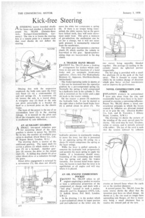
Dealing Dealing first with the suspension employed, the body rests upon the front axle • beam (1) via a cross-member (2) and coil springs (3). A transverse rod -(4) locates the axle in a lateral plane. A triangular stay (5) fixed to the axle can pivot universally in a bracket (6) fixed to a forward point on the chassis frame.
The basis of the patent is the use of an intermediate lever (7) in the steering linkage. It is located on the pivot axis (8) of the triangular stay, and, as a result. is•unaffected by axle deflection..
AN AUXILIARY GEARBOX
rtA SMALL two-speed reduction gear for mounting ahead of the main gearbox is shown in patent No. 78,5,924. By ifs -use, the number of available gear ratios is doubled. (Ford Motor Co., Ltd., 88 Regent Street, London, W.I.)
The drawing shows a section of the additional gearbox. The input shaft (1) carries a pinion (2) which meshes with a gear (3) on a layshaft. Another gearpair (4) returns.the drive to the output shaft (5). A sliding dog clutch (6) gives either direct drive or a reduction through the gears.
Direct drive engagement is acivatgd by a servomotor (7); 'this does not directly move the slider but compresses a spring (8). If there is no torque being transmitted, the slider moves, but as the gears have helical teeth, they will resist movement under load. This gives a measure of pre-selection; the mechanism can he set for a change, but it will not occur until pressure is momentarily removed from the accelerator.
The lower gear incorporates a one-way clutch (9) which enables the vehicle to free-wheel in this gear. Speed-synchronizing rings are incorporated in the dog clutch.
A TRAILER HAND BRAKE
PATENT No. 786,133 shows a braking arrangement for trailers which combines in one unit the functions of a hand brake and an automatic break-away applicator. (Tetra A.G. Fur Hydraulische Bremsen U. Apparate, Diellikon-Zurich. Switzerland.)
The brake-operating cable is shown at 1, this can be tensioned into the operative position by a pre-compressed spring (2). Normally the spring is held compressed by a hydraulic lock in the cylinder 3. The unit is mounted on the trailer and a pipe (4) leads to the tractor vehicle.
On the tractor a piston (5) maintains the hydraulic lock. It can be moved to the right when a hollow hand brake lever (6) is pulled about its pivot (7). The hydraulic pressure is continually tending to move the lever, but this is prevented by an opposing spring (8) acting via a chain (9) which compresses the spring as the lever swings.
When the lever is pulled upwards, it removes the hydraulic lock progressively and permits the main spring to apply the • brakes. If a breakaway should occur, fracturing of the connecting pipe would free the spring and apply the brakes instantly. For normal hand brake operation, the layout is such that the lever is in equilibrium at all angles and will stay where it is placed.
AN OIL ENGINE COMBUSTION POCKET
PATENT No. 786,329 refers to oil engines employing a pocket to receive at least a substantial proportion of the compressed air charge, and deals with a "hot plug" located in such a pocket. (Ricardo and Co. Engineers (1927), Ltd., 21 Suffolk Street, Pall Mall, London, S.W.I.)
In the drawing, 1 is the pocket which is part-cylindrical about its upper portion and part-spherical at the lower end, the wo curves being smoothly blended together. The passage (2) leading to the cylinder leaves the spherical portion tangentially.
The hot plug is provided with a small flat platform (3) in the path of the fuel spray. This is thought to create local eddies by its sudden change of direction which give better air-fuel intermixture and so improve the performance.
NOVEL CONSTRUCTION FOR TYRES
I NFLATION pressure in conventional tyres acts away from the rim, and inextensible bead wires have to be incorporated to exercise a restraining influence. Patent No. 786,162 shows a novel constructional principle in which the forces created by inflation arc directed inward so as to grip the rim. (Dunlop Rubber Co., Ltd., and H. Trevaskis, 1 Albany Street, London, N.W.1.)
The drawing (I) shows the pattern of the winding of the cord, spread open for clarity. The cord may be steel. Terylene, nylon or cotton, and is initially covered with rubber. The lay of the cord is such that the tension induced by inflation creates an inward force where the cords are at the smallest diameter.
A second patent, No. 786,163, from the same source shows the effect that the invention may have on wheel design. As shown at 2, the rim need no longer have upstanding side flanges, all that is necessary being a small abutment face to receive the inward pull of the tyre.


