


The Construction of Chassisiess Vehicles
Page 48
If you've noticed an error in this article please click here to report it so we can fix it.
A Resume of Recently Published Patent Specifications
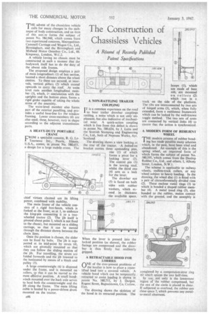
THE advent of the chassisless vehicle calls for many changes in the technique of body construction, and an item of this nal' re forms the subject of patent No. 580,940, which comes from two experienced concerns, MetropolitanCammell Carriage and Wagon Co., Ltd., Birmingham, and the Birmingham and Midland Motor Omnibus Co., Ltd., 88. Kingsway, London, W.C.2.
A vehicle having no chassis must be constructed in such a manner that the bodywork itself has to do the duty of the absent side frames.
The proposed design employs a pair of main longitudinal.; (1) of box section, located a short distance above the wheel centres. To these ate secured, at intervals, vertical pillars (2) which extend upwards to carry tile roof. At waist level runs another longitudinal member (3), which, i71 conjunction with the uprights and the bottom piece, forms a rigid girder capable of taking the whole stress of the assembly.
The waist-level member also forms part of the exterior panelling, and provides a useful base-line foi the window framing. Lower cross-members (4) are also used; these, however, vary in shape according to the adjacent transmission parts.
A HEAVY-DUTY PORTABLE CRANE
FROM a specialist concern, R. G. LeTourneau Inc., Peoria, Illinois, U.S.A., comes, in patent No. 580,653. a design for a large mobile crane. The
chief virtues claimed are its lifting power, combined with stability.
The main frame of the vehicle consists of a rigid box-beam, which is forked at the front, as at 1, to embrace the king-pin connecting it to a two. wheeled tractor (2). The jib itself is pivoted about point 3, which is not fixed to the chassis, but mounted on a sliding carriage, so that it can be moved through the distance shown between the chain lines.
Once the position is chosen, the slider can be fixed by bolts. The jib is supported at its mid-point by struts (4), which are pivotally mounted so that they can follow the sliding motion of the jib. For travelling, the struts are folded forwards and the jib lowered to he horizontal by means of a block and pulley (5).
A large counterweight (6) is disposed under the frame, and is mounted on rollers, so that it can be moved to the most effective position. A small handwinch mounted over the back axle serves to haul both the counterweight and the jib along the frame. The main lifting cable is hauled by a power-driven drum mounted on the tractor. A NON-RATTLING TRAILER COUPLING IT is a common experience on the road I to hear trailer drawbar couplings rattling, a noise "which is not only unpleasant, but also indicative of mechanical wear. A quick-action coupling which is free from this defect is shown in patent No. 580,624, by J. Latta and the Scottish Stamping and Engineering Co., Ltd., both of Neptune Works, Ayr. *Scotland.
The drawing shows a view looking at the rear of the tractor. A bolted-on bracket carries three upstanding pins, one (I) of which forms a pivot for a locking lever (2). The central pin (3) is the towing stud, whilst the third one (4) acts as a lock for the lever. The drawbar eye (5) is faced on both sides with rubber washers, which exceed in thickness the available space.
When the lever is pressed into the locked position (as shown), the rubber facings are compressed and the drawbar is thus firmly but resiliently griPPed
A RETRACTABLE HOOD FOR LORRIES
ONE of the ever-present problems of the haulier is how to place a cranelifted load into a covered vehicle. A vehicle hood which can be temporarily retracted to assist loading is shown in patent No. 580,711, by J. Dargan, Regent Street, Bagnalstown, Co. Carlow, Fire.
The drawing shows the skeleton of the hood in its retracted position. The hoops (I), which are made of bent ash, are mounted on rollers (2) which run in a track on the side of the platform. The ribs are interconnected by two sets of hinged arms (3), which, when fully extended, form a rectilinear framework which can be locked by the well-known toggle method. The two sets of arms are connected by vertical links (4) to ensure that the action is synchronized.
A MODERN FORM OF RESILIENT WHEEL
Ttr:has made possible many schemes modern process of rubber bond
which, in the past, have been tried and abandoned. An example of this is the spring wheel, an improved form of which forms the subject of patent No. 580.395, which comes from the Dunlop Rubber Co., Ltd., and others, 1, Albany Street, London, N.W.1.
The scheme is applicable to railway wheels, endless-track rollers, or any wheel subject to heavy loading. In the drawing, the wheel disc (1) is fitted with a pair of circumferentially divided rims (2). These enclose metal rings (3) to which is bonded a shaped rubber member (4). A metal tread ring (5), also bonded to the rubber, makes contact with the ground, and the assembly is completed by a compression-strut ring {6) which spaces the two half-rims.
In use, not only is the lowermost region of the rubber compressed, but the rest of the circle is placed in shear. If subjected to overload, the rubber can close space 7, which prevents any metalto-metal abutment.