


[Nat Form Will
Page 30
Page 31
Page 32
If you've noticed an error in this article please click here to report it so we can fix it.
THE GA
URBINE Take? By J. PICKLES, A.M.I.A.E.
THAT the gas turbine will eventually be used as a roadvehicle power unit is extiemely probable, although even the most staunch supporters of rotary power are forced to admit that several problems of first magnitude are still to be faced. Fuel consumptions in ground-level installations are still high, but only the fringe of the knowledge of this new principle has yet been touched.
In the gas turbine itself, much has been learnt from the efforts of the steam-turbine engineers, and although most of the larger units use similar blading forms, it cannot be assumed that the much smaller road turbine will follow suit. Any of the recognized blading principles may be adopted, or even an entirely new one.
Turbine design has, for steam operation, reached a high stage of development, and the gas-turbine engineer is fortunate in having a great deal of information from this source to draw upon. There are, however, several distinct systems of converting the kinetic energy of a rapidly moving fluid into rotative energy suitable for use in propelling a vehicle with greater or lesser efficiency.
Maintaining Combustion-chamber Pressure
Although most people will readily accept that steam, under pressure from a boiler, may be passed through nozzles and thence to a turbine wheel, many are somewhat at a loss to understand how pressure can be maintained in a combustion chamber, open at one end to the compressor, and at the other to the turbine. Any doubt on this score may be overcome by considering the compressor first to discharge into a closed vessel. It will then be obvious that pressure will be maintained to the extent of that at the compressor outlet, although there will be no flow. The presence of a suitably sized aperture discharging to the atmosphere will not cause loss of pressure.
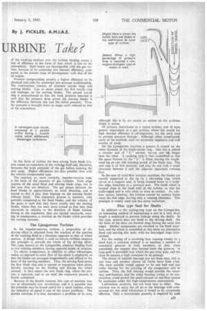
Two forms of nozzle are employed in turbines, the choice depending on the pressure drop required. When this pressure.drop is less than 40-50 per cent. of the combustion pressure, a convergent nozzle is used, consisting of a parallel orifice having a smooth radius to lead the gas without promoting turbulence.
When greater pressure drops than this are required, the convergent form is not satisfactory, and a convergent
divergent type must be used. This has a radiused entry to a narrow throat in which the maximum pressure drop obtainable in a convergent type is achieved. The further drop is obtained in a long trumpet-shaped extension, where an increased speed is achieved as the final expansion occurs.
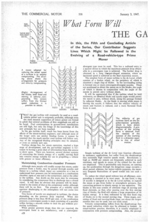
The simplest form of steam turbine is the de Laval, which consists of a bucket wheel, on the periphery of which is mounted a single ring of blades. In the surrounding casing is formed one or more convergent-divergent nozzles. These are positioned to direct the steam on to the blades, the angle of which is chosen in conjunction with the angle of the nozzle to permit entry without shock.
It will be appreciated that if the turbine wheel be held stationary, an identical blade and nozzle angle would permi: the steam to pass, without shock, along the passage formed by adjacent blades. As the blade is moving while steam is leaving the nozzle, it follows that the relative velocity of steam and buckets is reduced, and a more flattened blade form is used.
Simple turbines of the de Laval type function efficiently in stationary applications, but suffer from the disadvantage that extremely high rotative speeds result. Revolutions as high as 30,000 per minute are frequently achieved in such machines, and speeds in excess of the critical for the shaft are employed. This is permissible only because, on running up, the acceleration through the dangerous range occupies a short period, whereas, for motor-vehicle purposes, the necessary frequent fluctuations of speed would rule out such a unit.
To reduce the wheel speed without loss of efficiency, compounding is resorted to in most cases. In one form, a ring of nozzles is designed as in the de Laval turbine, to expand the steam or gas from boiler to atmospheric pressure, thus converting pressure to kinetic energy in one operation. The blades in this case consist of alternate rings of moving and fixed elements, so that, after passing over the first moving ring of blades, the fluid still retains a large proportion of its kinetic energy. It is then redirected by the first fixed ring of blades on to the second moving ring. Three stages, consisting of fixed and moving-blade rings, are about the largest number that can be used; two are most usual. • Velocity compounding suffers from the disadvantage that the speed reduction which may be obtained is limited. In steam-turbine practice, therefore, it is usually employed in conjunction with pressure compounding. Also, The passage
of the working medium over the turbine blading causes a loss of efficiency in the form of heat which is lost to the atmosphere. Such losses are incompatible with the gas turbine, because of its somewhat low thermal efficiency, compared, at the present stage of development, with that of the oil engine.
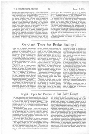
Pressure compounding permits a higher efficiency to be obtained and calls for somewhat less accurate workmanship. The construction consists _of alternate nozzle rings and moving blades. Gas or steam enters the first nozzle ring and impinges on the moving blades. The second nozzle ring is proportioned so that the back pressure imposed is such that the pressure drop across the moving blades is the difference between this and the initial pressure. Thus, the pressure is brought down in stages until reduced to that of the atmosphere.
In this form of turbine the heat arising from blade friction causes an expansion of the workiu fluid and, therefore, increases the work potential of the gas before entering the next stage. Higher efficiencies are thus possible than with the velocity-compounded type.
The reaction, or, more correctly, impulse-reaction type, is the basis of the majority of gas turbines. Each stage consists of the usual fixed and moving blade rings, but in this case they are identical. The gas passes between the fixed blades. in approximately an axial direction, and is turned so that it may then impinge on the moving blades without shock. The expansion process is, however, only partially completed at the fixed blades, and the velocity of the gases is such that they move axially into the moving blades, where they are once more turned so that they face rearwards in relation to the direction of blade motion. Owing to the expansion, they are ejected rearwards, causing, in consequence, a reaction on the blades which provides the turning moment.
The Ljungstrom Turbine in the impulse-reaction turbine, a proportion of the driving effort is obtained from the reaction of the ejection of the working fluid in a direction opposite to that of wheel motion. A design which is used on certain turbines employs this principle to provide the whole of the driving effort. This type, known as the Ljungstrom, employs blading fixed to two rotating members, having opposite hands of rotation.
To obtain compactness in addition to other advantages, radial, as opposed to axial, flow of the steam is employed, so that the blades are arranged longitudinally and affixed to the faces of the moving members. Thus, the driving fluid enters the first blade ring and is ejected as expansion takes place, thereby reacting on the blading and driving the wheel around. It then enters the next blade ring, where the process is repeated, and so on until the expansion process is finally completed.
Because of the double rotation, this type of machine may nil at abnormally low revolutions, and it is possible that the principle may be found useful for a small turbine, where the reduction of speed is one of the major problems. The double rotation, it is true, introduces a problem of its own,
although this is by no means so serious as the problem which it solves.
Of primary importance in a steam turbine, and of even greater importance in a gas turbine, where the search for high thermal efficiency is all-important, are the seals used to prevent pressure leakage. Although often complicated, some of the methods used are extremely ingenious and well worthy of study, On the ,Ljungstrom machine a groove is turned on the outer diameter of the blade-carrier ring, Into this is placed a circular seal of "U" section, having one let longer than the other. A caulking strip is then assembled so that the space formed by the "U" is filled, leaving the lengthened leg on one side standing proud of the blade ring_ This seal ring is of thin material, and may be run with a small clearance between it and the adjacent oppositely rotating face.
In the case of axial-flow reaction machines, the blades are usually supported at the tip by a shrouding ring, which serves as a support and, in being thinned down to a knifelike edge, functions as a pressure seal. The blade wheel is located close to the fixed wall of the turbine, so that the knife-edged seal is very close or even in contact. As rotation occurs, however, the friction caused by contact burns away the thin edge, leaving only a running clearance. This principle is widely used and has many variations, Disc type Seal for Shafts In addition to the sealing-ring type on the Ljungstrom, an interesting method of maintaining a seal in a very short length is employed to prevent leakage along the shafts. In this type, several discs are fitted to the driving shaft. On the faces of the discs are formed rings having the usual fine edges. Similar components are attached to the fixed stntctitre, and the whole is assembled so that there are alternative fixed and moving disc seals, with the fine-edged rings intermeshed.
For the sealing of a revolving face running closely to a fixed face, a common method is to machine a number of concentric grooves in both members, so that, when assembled, the tongues thus formed enter the grooves. A long path is provided over which the gas must pass, and the close fit ensures a high resistance to its passage.
The choice of suitable bearings has not been easy, and at one time and another almost all forms have been tried. The most suitable would appear to be one ball and one roller bearing for the carrying of the compressor and its turbine. Thus, the ball bearing would provide the necessary end-location, and the roller bearing, owing to its construction, could permit the small amount of end float caused by expansion under the high temperatures encountered.
Lubrication, similarly, has not been easy to effect. One solution was to spray the oil on to the bearings with compressed air, but solid lubrication is found to be completely effective. Only a microscopic quantity is required by each -bearing, and, in the writer's opinion, 'a small turbine Would best be lubricated bY a form of plunger pump injecting a small quantity of oil at infrequent. intervals.
The oil consumption of the gas turbine should be very low indeed, a factor which will help weigh the scales on the side of the turbine. There is, on present-day types, a large number of possible leakage points which must be reduced if fuel consumption, acceptable for road-vehicle work, is to be achieved. The theritial efficiency of the turbine is slowly being improved by careful study of the cornponents, but there is yet much to be done.
To increase thermal efficiency it will be necessary to raise zotnpressions above those at present employed, although the optimum efficiency, when using compressors of the turbine type, is achieved at pressures lower than those customarily employed in piston engines. , Compressor efficiency falls off with an increase in pressure, so that, at some point, the efficiency decrease of the compressor cancels out any improvement in thermal efficiency resulting from raising pressure ratio. For a compression ratio of 5:1 an efficiency of about 80 per cent. can be expected, falling to 75 percent. at 7:1. Somewhere between 7:1 and 6:1 represents about the limit within the scope of present knowledge.
A possibility for the improving of fuel consumption has been suggested, but it is by way of being a compromise scheme. A two-stroke engine would be so heavily supercharged that no power would be available at the crankshaft after that required for "blowing" had been deducted. The exhaust gases produced from this machine would be ducted to a turbine connected through the transmission to the road wheels. Although high efficiencies should be possible with this scheme, the bulk and vibration of the piston engine would still be present, and even if serious attention should be devoted to it, it could be considered only as an interim measure.
The other four articles of the series appeared hi the following issues.—September 20, October 18, November 8 and lilovernber 29.