


For DRIVERS, MECHANICS & FOREMEN.
Page 23
If you've noticed an error in this article please click here to report it so we can fix it.
A PRIZE OF TEN SHILLINGS is awarded each week all others are paid for at the rate of a penny a hue; with an published. Mention your employer's name, in onfi/lerice, Commercial Motor," 7-15, Bose to the sender of the best letter which we publish. on this page ; allowance for photographs. All notes are edited before bang as evidence of rood faith, Address, D., M. and F., !'The bery Avenue, London, E.C. 1.
Lamps Alight—
Light your lamps at 4.27 in London; 4.55 in Edinburgh, 4.25 in Newcastle, 4.39 in Liverpool, . 4.39 in Birmingham, 4.47 in Bristol, and 5.23 in Dublin.
A Handy Engine Stand for Use ot Ford Owners.
The sender of the following communication hat been awarded the 10s. prize this week.
[181S] "H.L." (Ryde) writes :—" I expect a great many of your readers. are misers of the popular Ford van, and that most of them will be interested in the following description and sketches of an engine stand by the use of which a considerable amount of time can be saved when•an engine overhaul is needed.
"'Some such shop fitting is very necessary, in my opinion, particularly in the case of the Ford engine, which requires delicate handling, owing to the fact that its magneto is built up in the engine case. The stand which I Faye made is not only a handy thing to use, but it has the additional advantage that it allows of the two men to work on the job together, without undue interference. This is generally very adVantageons as overhauls are almost invariably ` hurry jobs.'
"The construction is very simple 'indeed," as may be seen by reference to the sketch [Which we have had redrawn.—En.]. The important measurements are those of the portion on which the cylinder head stands. Frequently, as in my own case, a packing box of suitable dimensions may be picked up and utilized. The stand should be made long enough to allow of a couple of tin lids being nailed to the top to serve as receptacles for small parts, bolts, nuts, etc.
"To prepare the engine for the stand, simply remove the cylinder head ; turn it upside down, and place in position as shown on the sketch. The bigend bolts can be removed and the pistons taken out from below. All the main and connecting-rod bearings can be taken down and adjusted with a minimum of trouble with the engine in the position shown.
"There are one or two hints about the adjustment of Ford engine bearings which can very well be stated here. If the bearings Are not to be reinstalled, c145 not touch the surface with a tool. Take upfor wear by carefully filing down the faces of the joints. Do this little by little, trying the bearings frequently in place, so as to ensure that too much metal is not removed. When an engine has been running for some time, it Will be found that a hard skin has been formed on the surface of the white metal, and this skin, if left
untouched, will withstand an enormous amount of wear. If the skin be removed and fresh metal exposed to the action of the journals, the latter have to prepare for themselves a new surface on the bearings.
' "-When adjusting big-end bearings, do not remove the piston from the rod, but, each time the bearing is tried on the crankpin; allow the piston to enter the cylinder. If the big-end bearing is not being trued up square with the rod, the piston will bind in the cylinder, and thus give notice of the unequal adjustment."
Repairs to Road Roller Rear Wheels.
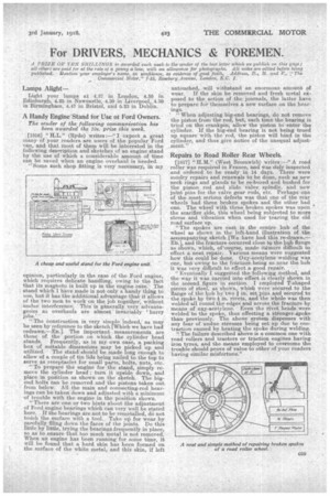
[1817] "H.M." (West Bromwich) writes :—" A road roller was required in France, and was duly inspected and ordered to be ready in 14 days. There were sundry repairs and renewals to be done, such as new neck rings and glands to be re-bored and bushed for the piston rod and slide valve spindle, and new joint pins for the valve gear rods, etc. Perhaps -one of the most serious defects was that one of the rear wheels had three broken spokes and the other had one. The wheel with three broken spokes was upon the scarifier side, this wheel being subjected to more stress and vibration when used for tearing the old road surface up. "The spokes are cast in the centre hub of the wheel as shown in the left-hand illustration of the acc,osnpanying sketch [We have had this re-drawn.— -Fit], and the fracture occurred close to the hub flange as shown, which, of'course, made it(more difficult to effect a neat repair. Various means were suggested how this could be done. Oxy-acetylene welding was one, but owing to the fracture being so near the hub it was very difficult to effect a good repair. "Eventually I suggested the following method, and the way it was carried into effe.ct is clearly shown in the second figure in section. I employed T-shaped pieces of Steel as shoWn,' which were secured to the flange of the hub by two in set Id.tis and secured to the spoke by two 4 in. rivets, and the whole was then welded all round the edges and across the fracture by means of oxy-acetylene. Even the rivet heads were welded to the spoke, thus effecting a stronger,spoke thanpreviously. The above system dispenses with any fear of undue stresses being set up clue to contraction caused by heating the spoke during welding.
" The failure described above is a common one with road rollers and tractors or traction engines having iron tyres, and the means employed to overcome the trouble should prove of value to other of your readers having similar misfortune!'