


Lightweight Mechanical Governor
Page 57
If you've noticed an error in this article please click here to report it so we can fix it.
ADDIT1ONAL to the standard range of C.A.V. mechanical governors, a new flyweight all-speed governor has been introduced by C.A.V., Ltd., Acton, London, W.3, which is smaller and lighter than existing types of centrifugally actuated model. This facilitates application to many engine installations normally equipped with a pneumatic governor because of space limitations.
Known as the S.P. type, the governor is available for all C.A.V. injection pumps in the AA range, and for some pumps in the N and NN ranges. The use of geartooth shaped contact points for the flyweights and their limited travel provide highly favourable governing characteristics at all speeds, control being particularly sensitive to idling-speed variations. The flyweights are mounted on the pump camshaft, and the main and idling speedcontrol springs are located on the shaft axis.
Maximum-fuel Stop
Special mention is made by the makers of the fact that the maximum-fuel stop is located in the governor housing, which discourages tampering by the vehicle driver or unauthorized personnel. The accelerator lever and the excess fuel control [ever (which also controls the stop shaft) can be arranged on either side of the governor.
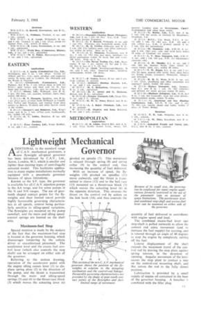
Referring to the section drawing, operation of the accelerator pedal with the engine idling causes lever (1) to displace spring plate (2) in the direction of the pump, and the thrust is transmitted through the mainand idling-speed springs (3) and (4) to the thrust-race block (5) which moves the actuating lever (6) pivoted on spindle (7). This movement is relayed through spring (8) and spring collar (9) to the control rod, thus increasing the quantity of fuel delivered.
With an increase of speed, the flyweights (10) pivoted on spindles (11) move outwards, and the thrust is transmitted to sleeve (12) and to the ball race (13) mounted on a thrust-race block (5) which moves the actuating lever (6) in the opposite direction. This reverses the thrust on the control rod by action on the fink hook (14), and thus controls the quantity of fuel delivered in accordance with engine speed and load.
The combined excess-fuel lever and stop-shaft is pulled outwards to allow the control rod extra movement (and to increase the fuel supply) for starting, and is rotated through an angle of 40 degrees to stop the engine by completely cutting off the fuel.
Lateral displacement of the shaft extends the maximum travel of the control rod by moving the stop plate against spring tension, in the direction of opening. Angular movement of the lever causes the stop plate to contact a step on the control-rod mounting shaft, and this moves the rod to the fully closed position.
Lubrieation is provided by a small supply of engine oil contained in the base of the governor housing. A breather is combined with the filler plug.