


Testing Gears for Tooth Form
Page 62
If you've noticed an error in this article please click here to report it so we can fix it.
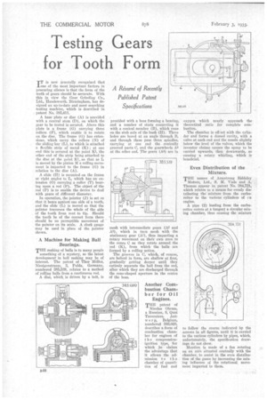
A Rdsumd of Recently Published Patent Specifications ITT is now generally recognized that of the most important factors in procuring silence is that the form of the teeth of gears should be accurate. With this in view the Gear Grinding Co., Ltd., Handswortla. Birmingham, has designed an up-to-date and most searching testing machine, which is described in patent No. 385,411.
A base plate or disc (A) is provided with a central stem (D), on which the gear to be tested is secured. Above this plate is a frame (G) carrying three rollers (F), which enable it to rotate on the disc. The frame (0) has extensions, which carry the rollers .(N) of the sliding bar (L), to which is attached a flexible strip of metal (K) ; at one end this is secured at the point K1, the other end of the strip being attached to • the disc at the point K2, so that as L is moved by the pinion M a rolling movement is imparted to the frame (G) in relation to the disc (A).
A slide (H) is mounted on the frame at right angles to L, which has an extension (0) carrying a roller (T) bearing upon a rod (P). The object of the rod (P) is to enable the device to deal with gears of different diameter.
In operation, the pointer (J) is set so that it bears against one side of a tooth, and the slide (L) is moved so that the pointer traverses the whole of the side of the tooth from root to tip. Should the tooth be of the correct form there should be no perceptible movement of the pointer on its scale. A clock gauge may he used in place of the pointer shown.
A Machine for Making Ball Bearings.
THE making of balls is to many people
something of a mystery, so the latest development in ball making may be of interest. The patent of Thor Willer, Niesigerstrasse, 3, Fulda, Germany, numbered 385,539, relates to a method of rolling balls from a continuous rod.
A disc, which, is driven by a belt, is
provided with a boss forming a bearing, and a number of studs connecting it with a conical member (B), which runs on the stub axle of the bush (H). Three holes are bored at an angle through B, and through .these pass three spindles, carrying at one end the conically grooved parts C, and the gearwheels A4 at the other end. The gears (A4) are in mesh with intermediate gears (A2 and A3), which in turn mesh with the stationary gear (214), thus imparting a rotary movement on their own axes to the cones C as they rotate around the rod (K), from which the balls are formed by a rolling action.
The grooves in C, which, of course, are helical in form, are shallow at first, gradually getting deeper until they entirely separate the ball from the rod, after which they are discharged through the cone-shaped aperture in the centre of the boss.
Another Combustion Chamber for Oil Engines.
THE patent of Nicolas Obram, a Russian, 8, Quai Taverniers, Antwe r p, Belgium, numbered 385,020, describes a form of combustion chamber for engines of the compressionignition type, for which he claims the advantage that it allows the admission to the chamber of quantities of fuel and oxygen which nearly approach the theoretical ratio for complete cornbustion.
The chamber is off-set with the cylinder and forms a domed cavity, with a valve at each end and the nozzle slightly below the level of the valves, which the inventor claims causes the spray to be carried upwards, then downwards, so causing a rotary whirling, which is beneficial.
Even Distribution of the Mixture.
THE names of Armstrong SicIdeley
Motors, Ltd., S. M. Vials and A., Thomas appear in patent No. 384,721; which relates to a means for evenly distributing themixture from the carbu-• retter to the various cylinders of rn engine.
A pipe (2) leading from the carbn-. retter enters at a tangent a circular mixing chamber, thus causing the mixture
to follow the Course indicated by the arrows in all figures, until it is carried to the various cylinders by pipes, which, unfortunately, the specification draw ings do not show. •
Mention is made of a fan rotating on an axis situated centrally with the chamber, to assist in the even distribol tion of the gases by increasing the mixing influence of the rotational. movement imparted to them.