


Interesting Developments with
Page 46
Page 47
If you've noticed an error in this article please click here to report it so we can fix it.
A BRITISH FUEL PUMP
IT is possible this week to place before our readers full information concerning the activities of Bryce, Ltd., Kelvin Works, Hackbridge, Surrey. Backed by important industrial interests, this company has, during the past year or two, been developing a new type of injection pump and nozzle of British design for oil engines, and has established at Each-bridge a production plant embodying only the latest machines and capable of extensive development.
The equipment is available for stationary, marinc and road-vehicle oil engines, and the pump, which is of the plunger type, is supplied either complete with camshaft, or in non-camshaft form, for engine makers desiring to use their own camshafts. The range covers stroke dimensions of from * in. to 1136 in., of which # in. is the normal stroke for • road-transport units, and plunger diameters from 0.2 in. to 0.390 in., of which an intermediate size of 0.3125 in. (,;, in.) is the standard for engines with which our readers are familiar. Single-cylinder pumps are available in plunger bores up to 0.781 in.
Moderate Size One of the Leading Features of the Bryce Pump.
An important feature is the moderate length of the camshaft, the plunger centres of the standard model being 1.008 in. (25 mm.) apart, although a special model can be provided with 40-mm. centres. Production is already well advanced, the modern plant being almost entirely British, and the units are made to inch dimensions.
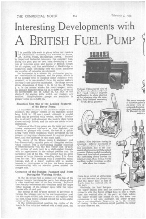
Features of the Bryce pump are the large port areas (giving maintained efficiency at high speeds), the absence of plunger side thrust, the use of a quickacting valve which eliminates waste movement on the plunger (giving bigger displacement for a given plunger Size), and the shortness of the main shaft.
The sleeve of the Bryce pump is stationary and has diametrically opposite ports of triangular section, which connect with a surrounding annular reservoir in communication with the fuel supply and by-pass. The section of each port is a right-angled triangle with its hypothenuse in the oblique position and the horizontal side at the top. The plunger has an axial passage of large diameter extending about a in. clown from the top. This connects with a transverse radial Passage, and, at a lower position," with a similar passage at right-angles to the first, the lower passage communicating with an annular groove around the plunger side.
Operation of the Plunger, Passages and Ports -During the Working Stroke.
On the up stroke fuel is spilled over the top of the plunger through the triangular ports, their shape giving a large discharge area to the last moment. Injection then sharply commences and continues until the upper radial passage of the plunger opens with the hypothenuse side of each port.
The timing of this by-pass opening 18 governed by turning the plunger, and an the maximum-output position the upper drilled hole does not -at all register with the port, being turned around beyond the acute-angled corner of the triangle.
In the minimum-output position the centre of the hole is in line with the vertical side of each port, and B32 there is no output at all because the land between the plunger top and the upper hole is less in depth than the vertical side of. the port.
Similarly, the land between the upper drilled hole and the annular groove that connects with the lower dril*d hole is less in depth than the vertical side of the port, so that, before the upper by-pass has ceased to act, the lower one commences to act and, obviously, the lower by-pass has a correspondingly large area up to the moment of closing. In the maximum-output position the upper by-oass does not act. The large area of the ports just before closing gives a low velocity to the by-passed fuel, thus reducing the tendency of the fuel to froth. The low velocity also reduces the tendency, if any, for the right-angled edge of the plunger crown to ridge the wall of the sleeve, although it will be clearly seen that the plunger is balanced.
An ingenious arrangement, incorporating a collar which fits with 0.003-in, clearance, relieves the plunger of the spring load throughout its upward stroke, and, except for any ,lag behind the earn, throughout its downward stroke. In practice there can be no material lag, because the plunger is at all times easily turned.
The tappet design, again, shows ingenuity in that its base incorporates a, roller that turns in a transverse hole, from which rather less than half its periphery protrudes to engage with the cam. The roller is positioned endwise by the lower bush.
On the upper surface of the tappet is an orthodox adjusting screw, on which rests an inverted thimble, which engages with the lower collar (referred to above) that relieves the plunger of the spring load. Where the injection-timing rack passes through the aluminium pump body at each end a bush is fitted, and the bushes may be replaced without dismantling the pump.
Advantages of the Big-area Ports and Quickacting Valve.
The design of the cylinder head and plunger is claimed to have the effect of ridding the pump of any air, partly because of the smooth by-pass flow and partly because of the design of the quick-acting valve.
Easy starting is claimed, due to the absence of leakage kt full-supply position, the upper by-pass hole being then more than one diameter away from the acute-angle corners of the ports; the latter is important because the plunger velocity near the top of its stroke is low,. For the same reason a good maximum power may be expected and there should be a sharp injection commencement and cut-off, giving silence and fiexi bility.
High speeds are facilitated by the big port areas, especially at the closing point, also by the accurate metering obtained through lack of frothing tendency.
The pump for six-cylindered road-transport engines measures 5-4ins, over the six bore centres, and has an overall length of 8 ins., increased to 12i ins, when the Bryce high and low-speed governor is fitted.
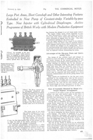
Ease of Assembly Obtained by Means of a Simple Register Arrangement.
A featureof the pump is that all fuel passages are drilled, not cast, and another point is that there is nothing to adjust when assembling. The sleeve is dowelled into position in the ease, and a pinhole for the turning dog is drilled, in the plunger, in relation to the upper by-pass. The plunger is easily produced.
Timing also is simplified because a mark on the casing shows where one of the plungers opens at a given pressure. Driving and driven sleeves, having helical grooves cut in opposite directions, are connected by a collar, on the inner face of which are six bronze pads which fit in the grooves, so that movement of the collar gives double action, resulting in a compact unit.
An aim in designing the Bryce injector has been to avoid leakage. The needle is connected to a corrugated cylindrical diaphragm and pressure builds up on the outside of this, lifting the needle off its seat so that the diaphragm takes the place of a spring. Any type of nozzle can be fitted, and the company will shortly be producing various types. The lift of the needle is limited by an adjustable screw and the lifting pressure is governed by screwing down and locking a collar that depresses the upper end of the diaphragm. This' screw collar has a soft copper washer acting as a gland, so that no fuel can get behind the diaphragm to cause pressure balance.