


UTILIZING HEAVY FUEL IN ORDINARY ENGINES.
Page 28
If you've noticed an error in this article please click here to report it so we can fix it.
A Resume of Recently Published Patent Specifications.
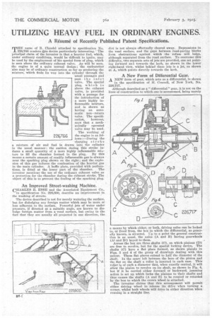
TIIE name of R. Claudel attached to specification No. 226,766 renders.khis device particularly interesting. The principal claim of the inventor is that a heavier fuel, which, under ordinary conditions, would be difficult to ignite, may be used by the employment of his special form of plug, which is seen above the ordinary exhaust valve. As will be seen, the engine is of a quite normal design ; the carburetter also may be of ordinary construction so far as producing the mixture, which finds its way into the cylinder through the usual passages and past the inlet valve. The special plug, which is above the exhaust valve, is provided with a passage for the introduction of a more highly inflammable mixture, and is shown as having an automatic nonreturn valve. The specification, however, says that a mechanically operated valve may be used The working of the engine is as follows :—During the charging stroke a mixture of air and fuel is drawn into the cylinder in the usual manner : the suction during this stroke induces a small quantity of a more highly inflammable mix
ture to fill the chamber formed in the plug. By this means a certain amount of readily inflammable gas is always near the sparking plug shown on the right; and the explosion of this gas induces the combustion of the heavier gas in the main cylinder. A bailie plate, provided with perfora tions, is fitted at the lower part of the chamber. The inventor mentions the use of the ordinary exhaust valve as a protection for the chamber during the exhaust stroke. The object of this is to prevent the fouling of the sparking plug.
An Improved Street-washing Machine.
CHARLES E. ESSE and the Associated Equipment Co., in specification No. 226,600, describe an improvement in the washing of streets.
The device described is not for merely watering the surface. but for dislodging any foreign matter which may be more or less adherent to the surface. Powerful jets of water under pressure, if directed at a suitable angle, are known to dislodge foreign matter from a road surface, but owing to the fact that they are usually all projected in one direction, the dirt is not always effectually cleared away. Depressions in the road surface, and the gaps between road-paving blocks form obstructions against which the refuse will lodge, although separated from the road surface. To overcome this difficulty, two separate sets of jets are provided, one set pointing forward and towards the kerb, as shown in the lower right-hand view, whilst behind these jets is a jet, as shown at A, which points directly towards the kerb.
A New Form of Differential Gear.
A NEW form of gear, which acts as a differential, is shown in the specification of H. Connell, of New York, No. 226,717.
Although described as a " differential" gear, it is not on the lines of construction to which one is accustomed, being merely a means by Which either, or both, driving axles can be locked to, or freed from, the box in which the differential, as generally known, is situated. lip to a point the general construction is as usual, the axles (A and B) having gearwheels (Al and B1) keyed to them.
Across the box are three shafts (C), on which pinions (D) are free to revolve, but for the special locking device. The shafts (C) have a flat place formed, as shown plainly in Figs. 3 and 4 of the group of drawings dealing with this patent. These flat places extend to half the diameter of the shaft. In the space left between the bore of the pinion and the flat on the shaft a roller is inserted in each case. This roller is of such a diameter that, when exactly central, it will allow the pinion to revolve on its shaft, as shown in Fig. 4, but if it be carried either forward or backward, jamming action is set up which locks the pinions to their shafts and thus causes the shafts (A and B) to be rotated or retarded by the box to which the crown wheel is attached.
The inventor claims that this arrangement will permit either driving wheel to release its drive when turning a corner, whilst both wheels will drive in either direction when running in a straight line.