


THE LANDON-MARTYN TURNING GEAR.
Page 9
If you've noticed an error in this article please click here to report it so we can fix it.
A Description of an Interesting Device Which Enables Motor Vehicles to Manoeuvre in a Confined Space.
rrET.E MOTOR VEHICLE as designed 1 for commercial work has few disadvantages, but one of them is that if a number of lorries are parked closely to, gether, say, in a railway yard, and in an end-on direction, as sometimes happens, it is difficult, and sometimes almost
individual impossible, for an individual vehicle to leave its position without a. considerable amount of tricky manipulation.
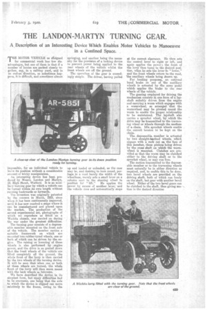
An interesting device has been produced by Messrs. Landon and Martyn, 18, High Street, Watford. It is an auxiliary turning gear by which a vehicle can be turned within ifs own length without running backwards or forwards. The invention was originally patented by the concern in March, 1915, since when it has been continuously improved, until it has now reached a stage where it can be manufactured and placed upon the market. The production of the second experimental set, photographs of which we reproduce as fitted on a Wichita chassis, was carried on during the war under the greatest difficulties.
The turning gear consists of a depressable member mounted on the front axle of the vehicle. The member carties..a suitable , framework on which a,re mounted two rubber-tyrecl wheels, one or both of which can be driven by the engine. The raising or lowering of these wheels is also performed by engine power, and the drive is so geared down that the front wheels of the vehicle are lifted completely off the ground, the whole front of the lorry is then carried by the two wheels of the turning device; It will. be seen that when one or both of these wheels are turned, the whole front of the lorry will then move round with the back wheels as fulcrums.
We have described the device in its simplest form, but many difficulties had to be overcome, one being that the axle to which the device is clipped can move relatively to the frame, owing to the springing, and another being the necessity for the provision of a locking device to prevent power being applied to the rear wheels of the vehicle whilst the front wheels are off the ground.
The operation of the gear is exceedingly simple. The driver, having pulled up and loaded or unloaded, -as the case may be, and desiring-to turn round, perhaps in a road barely .the width of the wheelbase, merely sets a small lever on a column next to the steering wheel to
position for " He applies the -power by means of another lever,and the vehicle rises and automatically stops at the correct clearance, lie then sets the control lever to right or left, and again applies the power; the front of the lorry then turns to the desired position, when he sets the lever to " lower," and the front wheels return to the road, 'the auxiliary wheel's being drawn up.
For braking purposes, an external band brake on one of the auxiliary wheels is actuated by the same pedal which applies the brake to the rear wheels of the vehicle.
The gearing employed for driving the mechanism consists in one form of a layshaft suitably driven from the engine and carrying a worm which engages with wormwheel, so arranged that the wormwheel may be pivoted round the worm to enable the proper relationship to be maintained. The layshaft also carries a sprocket wheel, by which the drive may be transmitted to the traversing wheel or wheels through the medium of a chain. Idle sprocket wheels enable the correct tension to be kept on the chain.
The, depressable, member is actuated by twa straight.toothed wheels, which engage with a rack cut cm tho face of this member, these pi-niona being driven by the cross shaft on which the wormwheel is mounted. Clutches are provided so that the worm may be clutched either to the driving shaft or to the sprocket wheel, or may run'free.
The motion transmitted to the depressable member or to the traversing wheels must naturally be in either direction as required, and, to enable this to be done, two bevel wheels are provided on the driving shaft, both of which run freely on the shaft, but gear with another bevel wheel. Either of the two bevel gears can be clutched to the shaft, thus giving motion in the desired direction