


HOW FAR Flik SUSPENSION PROGRESSED ?
Page 34
Page 35
Page 36
If you've noticed an error in this article please click here to report it so we can fix it.
Asks L. J. COTTON, M.I.R.T.E.
No extraordinary dinner, nor any other entertainment good, but afterwards to the trial of some experiments about making of coaches easy. And several we tried; but one did prove mighty easy, not here for me to describe, but the whole body of the coach lies upon. one long spring, and we all, one after another, rid in it; and it is very fine and
likelyto fake. . .
THIS &tract from Samuel Pepys's diary aptly summarizes one of the earlier of the laminatedspring systems which to-day are employed in most commercial vehicles. It would be difficult to find any component of a chassis which is so hard-worked as the springs At•first, it may appear easy to devise, by calculation;. a 'spring which will be serviceable within a
range of, for example, 6 to 12 tons, and a main and auxiliary spring would probably fulfil the requirements. Add to the load all the variations caused by irregular road surfaces, torque reactions when braking, or accelerating, overloading, and torsional stresses when cornering, and the problem becomes highly complicated.
Should the suspension be too soft, the wheels would foul the body and the vehicle would be unstable when cornering. Spring fractures would be frequent, and riding conrIfort would be marred by excessive body roll. Harsh suspension, besides being unpleasant to the driver and passengers, ultimately affects the life of the body and chassis. Road shocks transmitted to the body cause fatigue and wear on the chassis frame, and increase movement of the body structure. Driving fatigue is increased because all road shocks are transmitted through the steering gear to the steering wheel.
. In earlier days, springs comprised a large number of narrow steel leaves, cambered almost to a semi-circle, with a large rubber volute pad or helical fiat-section spring to take care of overloading. Such a system could be defined only as a blacksmith's effort, in a comparison with the arrangements seen on vehicles at the London and Paris shows.
Gone are the days when the blacksmith maliciously hammered a spring plate and tempered it, • using an ash stick as his pyrometer. Springs to-day are sci en t i fl c achievements and manufacturers have succeeded in producing leaves that are homogeneous and correctly grained, even to the material in the eye of the main plate.
A visit to one of the big spring factories is sufficient to demonstrate the highly specialized nature of spring manufacture, assembly and testing. Samples taken from the material entering the factory are analysed, and are required.to conform with a rigid specification before being passed for production. The plates are formed on dies, and the heat treatment is scaled to a production basis in heat-controlled ovens. The leaves are tested for hardness before assembly.
Alter assembly, the complete spring is subjected to a scragging test, which comprises overloading almost to the point of yield. This nestles the leaves together, and affords a check against failure by fracture. The assembly is then passed for Static and load deflection, which is again observed between closely controlled limits.
Broadly speaking, that is the process of production, although there are many variations of construction to suit the vehicle manufacturer's requirements. The goods-vehicle spring may generally be said to be of higher standard than that of a passenger vehicle, which can rely upon shock absorbers and torsion bars to assist in its suspension. The tendency in modern design is to specify springs up to 6 ft. long, with very wide leaves.
Weldless Solid Eye
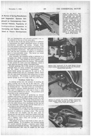
In making spring eyes, the practice of bending the plate is giving way to the use of the solid eye. The Brockhouse concern uses the electrical upsetting method of forming the eye. The leaf is first cut overlength by the necessary amount, heated electrically at its extremities, and is compressed at each end to form a solid mass of metal sufficient for an eye. This produces good grain flow at the required points.
The Woodhead method of producing an all-steel weldless solid spring eye again affords correct graining. Other specialities of Woodhead design include the solid lug plate and rebound clip, the lugs being formed in the solid steel spring plate. The triangular-section clip used with this plate ensures firm attachment of the top leaf to the remainder of the spring, and the whole acts as a solid beam in the rebound after shock.
Divided-back-plate springs have been devised to perform the function of a radius rod and torque-reaction • member, in addition to carrying a load. The top leaf is divided into two lengths, and the inner ends are pinned into the side plates, which have integral bolt legs. The effect is to convert the top leaf at the anchored end into a definite radius road, and provide a positive location for the axle.
. This pattern of spring is used freely in fourand sixwheeled vehicles. In six-wheelers, two inverted springs are usually secured through a common centre block containing the bogie-pin bearing. The popularity of the ditided-batk-plate unit may be judged by the large _numbers shown, fitted to trolleybuses and heavy vehicles at Earls Court. Trolleybus operation, because of high initial torque, makes heavy demands on the suspension, which are met by the two-spring system.
Another interesting example of spring design is the trunnion swivel end. In the conventional spring, the twist caused by road irregularities is either transmitted to the frame or absorbed within the spring. Particularly with heavy vehicles, which have rigid frames, the whole twist has to be taken by the spring, and this, added to normal stresses, frequently produces the crack which ultimately ends in a complete plate fracture. The spring with a single or double trunnion end permits a predetermined movement of the axle, without transmitting twists to the plates, the rotary mevement being cared for by the trunnion's swivelling on its bearings.
There have, in minor ways, been other advances in design, including the fitting of helper arrangements, continuation of the second leaf to act as a support around the spring eye, shot peening and interleaving with anti-corrosive and lubricating materials. Helper springs
are to be found on most of the medium and heavy vehicles, and may be considered a necessity where no other arrangements are made for the suspension of widely varying loads.
Tippers, for example, normally carry a full load in one direction, and return light. Obviously, the suspension system would have to be planned for a full load, and, if no auxiliary arrangements were made, the vehicle would be unstable when running light. In a like manner, passenger vehicles have to be sprung to afford smooth travel whether operating with a small or full complement of passengers. Again, the need is fulfilled by spring phasing. An example of phasing is to be observed in the new Bristol M-type passenger chassis.
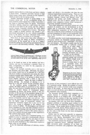
In the auxiliary spring arrangements of British vehicles, the helper plates are positioned to bear against either the main leaves or brackets secured to the chassis frame. A curious feature of Continental design, exemplified by Saurer and Somua chassis, is the construction of the top leaf of the secondary spring to bear directly against the flange of the frame side member.
To help standardization, in vehicle design, the same chassis is frequently used for light vans and cars. This practice has introduced independent suspension systems into the lighter range of commercial vehicles, and technicians' comments suggest that it may not be long before this system is extended to the medium and heavy classes of vehicle. The Birmingham and Midland Motor Omnibus Co., Ltd., and other transport concerns, are already experimenting with this form of suspension in their chassis, and it is known that certain manufacturers have reached advanced stages in their experiments with medium-sized goods vehicles.
In the event of a fracture in a laminated spring, it is unlikely to occur in every plate simultaneously, whereas with a coil spring, which has only one piece of metal, a fracture would cause complete failure. This appears to be the main drawback to the independent suspension which relies on coil springs.
It has the important adyantages of reducing unladen
weight and affords a far—smoother-ride than -the ,conventional longitudinal laminated spring. Those on view at the London and Paris shows, such as the Austin, Bedford, Commer, Citroen and Renault 4-cwt. van, employed coil springs and double wishbones. The Renault 6-cwt. van and Q electric vehicles have independent front suspension systems which incorporate a transversly mounted laminated spring.
Four-wheel independent suspension systems set a high standard of comfort, and the developments in the Q vehicle and in Continental design are worth noting. With independent suspension on the driving wheels, there may at first be certain problems of universal joints and their protection, but these are not insuperable. Many cars on the Continent have employed this system for many years.
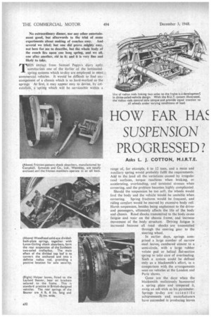
To obtain smoother travel, both laminated-spring and coil-spring systems are frequently assisted—perhaps it would be more correct to say "controlled "—by torsion bars and dampers. The dampers usually take the form of spring-loaded friction pads or hydraulic cylindefs which are of either singleor double-acting pattern. Shock absorbers control the periodicity, of the spring by retarding its potential movement and acting as a buffer on the rebound.
Torsion bars are, in effect, an additional spring, and, provided that sufficient length could be accommodated within the chassis to enable them to work at a reasonable stress, they could replace the conventional laminated spring. The torsion bar is expensive to machine, and the process of heat treatment is more difficult than that of a laminated spring. Besides the problem of accommodating such a unit, a fracture would cause complete failure of the system. In most cases, the torsion bar is used as an anti-roll device, and is effective in controlling the suspension when cornering.
The Scammell Scarab front-wheel suspension is of interest because it combines 'coil springs and a hydraulic damper as an integral unit. It is possible to combine the two systems in this case because of the more or less constant load carried by the front wheel.
Six-wheelers with twin rear drive have presented to designers problems of providing equal traction to the four wheels under all conditions of loading, acceleration and braking. Three models shown at Earls Court—the Thornycroft S.A.R. chassis, Dennis Jubilant and B.U.T. trolleybus—revealed that the use of radius rods linking the two axles to the frame was the latest development in this connection.
Rubber may he used more generally in suspension systems of the future. The Rotoflo, made by Universal Dampers, Ltd., Shirley, Birmingham, uses a form of uncured synthetic rubber in a vane-pattern damper.
The Metalastik concern has devised a rubber-bonded toggle-link suspension layout. Although responsive to slight movement under conditions of no load, the suspension is non-linear and progressive with loading.