


A Novel
Page 62
If you've noticed an error in this article please click here to report it so we can fix it.
Rotary Engine
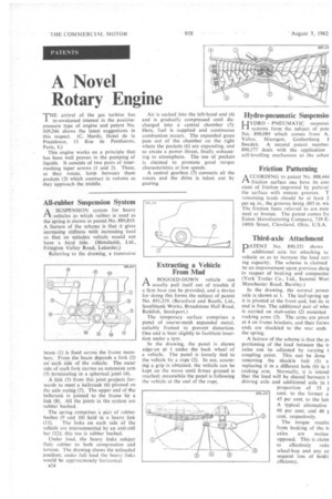
THE arrival of the gas turbine has re-awakened interest in the positivepressure type of engine and patent No. 889,246 shows the latest suggestions in this respect. (C. Hardy, Hotel de la Presidence, 13 Rue de Penthievre, Paris, 8.)
This engine works on a principle that has been well proven in the pumping of liquids. It consists of two pairs of intermeshing taper screws (1 and 2). These. as they rotate, form between them pockets (3) which contract in volume as they approach the middle. Air is sucked into the left-hand end (4) and is gradually compressed until discharged into a central chamber (5). Here, fuel is supplied and continuous combustion occurs. The expanded gases pass out of the chamber on the right where the pockets (6) are expanding, and so create a power thrust, finally exhausting to atmosphere. The use of packets is claimed to promote good torque characteristics at low speeds.
A central gearbox (7) connects all the rotors and the drive is taken out by gearing.
Hydro-pneumatic Suspensio
HYDRO PNEUMATIC suspensil systems form the subject of pate No. 890,089 which comes from A. Volvo, Hisengen, Gothenburg 1 Sweden. A second patent number 890,177 deals with the application self-levelling mechanism to the schen
All-rubber Suspension System
riA SUSPENSION system for heavy vehicles in which rubber is used as the spring is shown in patent No. 889,819. A feature of the scheme is that it gives increasing stiffness with increasing load so that• an unladen vehicle would not have a hard ride. (Metalastik, Ltd., Evington Valley Road, Leicester.)
Referring to the drawing, a transverse
beam (1) is fixed. across the frame members;-, Front.the beam depends a fork (2) on each side of the vehicle. The outer side of each fork carries an extension arm (3), terminating in a .spherical. joint (4)..
A-link (5) from this joint projects forwards to meet-a bellcrank (6) pivoted on the axle casing (7). The upper end of the bellcrank is jointed to the frame by a link (8). All the joints in the system are rubber bushed.
• The spring comprises a pair of rubber bushes (9 arid 10) held in a heavy. link (11). The links on each side of the vehicle are interconnected by an anti-roll bar (12); this too is rubber bushed.
Under load, the heavy links subject their. rubber to both compression and torsion. The drawing shows the unloaded position; under .full load the heavy links would be approximately horizontal.
Extracting a Vehicle. FromMud
ABOGGED-DOWN vehicle can usually pull itself out of trouble if a firm base can be provided, and a device for doing this forms the subject of patent No. 891,239. (Beresford and Booth, Ltd„ Southbank Works, Broadstone Hall Road, Reddish, Stockport.)
The temporary surface comprises a panel of coarse-mesh expanded metal, suitably framed to prevent distortion. One end is bent slightly to facilitate insertion under a tyre.
In the drawing, the panel -is shown edge-on at 1 under the •back wheel of a vehicle. The panel is loosely tied to the vehicle by a rope (2). In use, assuming a grip is obtained, the vehicle can be kept on the move until firmer ground is reached; meanwhile the panel is following the vehicle 'at the end of the rope.
Friction Patterning
ACCORDING to patent No. 888,444 friction surface can have its codl cient of friction improved by patterni the surface with minute grooves. T remaining lands should be at least 2 per sq. in., the grooves being .005 in. wic The friction faces referred to are mos steel or bronze. The patent comes fre Eaton Manufacturing Company, 739 E 140th Street, Cleveland, Ohio, U.S.A.
Third-axle Attachment
DATENT No. 890,333 shows
additional axle for attaching to vehicle so as to increase the load can ing capacity. The scheme is claimed be an improvement upon previous desig in respect of braking and compactne (York Trailer Co., Ltd., Summit Wonl Manchester Road, Burnley.) In the drawing, the normal power axle is shown at 1. The leaf-spring up it is pivoted at the front end, but its ix end is free. The additional pair of whe is carried on stub-axles (2) mounted rocking arms (3). The arms are pivot at 4 on frame brackets, and their forwa ends are shackled to the rear ends the spring.
A feature of the scheme is that the pi portioning of the load between the ti axles can be adjusted by varying t coupling point. This can be done removing the shackle bolt (5) a replacing it in a different hole (6) in t rocking arm. Normally, it is intend that the load will be shared between t driving axle and additional axle in proportion of 55 I cent, to the former a 45 per cent, to the latt A typical alternative 60 per cent. and 40 I cent. respectively.
The torque reactic from braking of the t.1 axles are mutua opposed. This is claim to effectively redo wheel-hop and any co sequcnt loss of braki efficiency.