


Driving Large Bogies
Page 68
If you've noticed an error in this article please click here to report it so we can fix it.
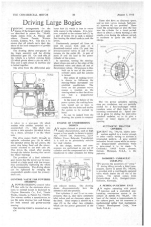
['RIVING arrangements for the LI bogies of the largest sizes of vehicle are described in patent No. 750,403, which comes from A. Wilson and others, Cinema Parade, Western Avenue, London, W.5. The aim is to ensure that all wheels carry their due share of the load irrespective of ground inequalities.
The drawing shows one-quarter of the bogie assembly and the driving differential gear (1). On each side of the vehicle is a hollow rocking beam (2) which pivots about a pin on axis 3. This unit is split about its mid-line and is bolted together.
The drive from the differential gear
is taken to a spur-gear -,(4) which meshes with another mounted on a countershaft (5). This shaft also carries a twin sprocket (6) which drives, via a chain, sprocket 7 on the wheel axis.
The drive passes finally through an epicyche reduction gear (8) in which the sprocket drives the sun pinion, the outer ring being fixed and the planetcarrier attached to the stub axle (9). This drives the wheel, after passing through the tubular housing that carries the wheel bearings.
The provision of a final reduction gear means that the power can be transmitted at a high speed with low torque, thus considerably lightening the whole of the transmission. The driving chains can be tightened by swinging the countershaft spindle about the primaryshaft axis.
CONTROL VALVE FOR POWERED STEERING
APOWER-STEERING control valve that calls for the minimum alterations to normal layout is disclosed by Clayton Dewandre Co., Ltd., Titanic Works, Lincoln, in Patent No. 750,393. The scheme enables a manufacturer to use the same steering box and linkage for both normal and power-assisted steering.
The steering-wheel is mounted on an A34 outer hub (1) which is free to rotate
rvith respect to the column. It is, hower, coupled to the column hub (2) by pair of levers (3) in such a manner that turning the wheel tends to rock the !evers. Continuously pumped oil from an inlet (4) passes both ends of a irectional-control valve (5), past two pressure-control valves (6 and 7) and scapes via the outlet (8). A pair of sorts (9 and 10) lead to ihe power ylinder of the system.
In operation, turning the steeringwheel closes one end or the other of the directional valve and shuts off one of the pressure valves. Oil pressure is thus built up in one of the powercylinder pipes and the column is turned.
The action of rocking levers is always to follow-up the steering-wheel movement and establish equilibrium. The force on the pressure valves causes a reaction on the steering-wheel so that the driver can feel a proportional _resistance.
In the event of failure of the power system, the rocking-lever tails would act as keys to couple the two hubs and enable the system to be worked by hand.
As can be judged from the drawing, the system is compact.
ENGINE OF UNORTHODOX DESIGN
ik N engine claimed to possess steam.C1 engine characteristics, such as high torque at low speeds, is shown in patent No. 750,493 (M. Nestorovic, 2211V Obilicev Venac, Belgrade, Yugoslavia). It is said to be particularly suitable for road vehicles.
In this design, suction and compression are performed in one set of cylinders and the compressed air is then transferred to other cylinders for firing
and exhaust strokes. The drawing shows diagrammatically how the scheme is put into practice.
Two cylinders (1 and 2) act as compressors; that is, they have automatic inlet valves and no clearance space in the head. Their output is ducted by a pipe (3) to the other two cylinders which are the power generators of the engine.
These also have no clearance space, and no inlet valves; instead, fuel-cumair injectors (4) are provided. These inject the compressed air plus the fuel into the cylinder for a timed period. 'I here is always a flame burning at the nozzle, even during the exhaust period, in readiness to ignite the next full charge.
The two power cylinders operate" once per revolution, and are partially cooled by a heat-exchanger which transfers some of their heat to the incoming compressed air. Speed control is given by sliding the inlet-valve camshaft endwise, so as to give a greater or lesser degree of valve opening.
AUTOMATIC TRACTOR CONTROL
PATENT No. 750,542, shows automation applied to a tractor plough • or other vehicle having to traverse •a preselected pattern. A gyro control. maintains the set course whilst an accurate distance-meter determines when a turn-round is to be made. S. Ovshinsky, 19935 Forrer Avenue, Detroit,, Michigan, U.S.A., is the patentee.
MODIFIED HYDRAULIC COUPLING
TO prevent the possibility of " creep" 1 during idling periods, a fluid transmission, shown in patent No. 748,146, is provided with a centrifugally operated valve which drains the oil out of the system. The patent comes from Daimler-Benz A.G. Stuttgart-Lintertitrkheim, Germany.
• A PETROL-INJECTION UNIT
AN engine operating with petrol injection and a controlled nonknocking combustion system is the subject of patent No. 750,265. The basis of the patent is improvements in the exhaust ports, but the treatment is mathematical rather than mechanical. (Texaco Development Corp., New York, U.S.A.)