


.EW GARDNER ENGINE FOR TH UGH-PERFORMANCE VEHICLES
Page 26
Page 27
Page 28
If you've noticed an error in this article please click here to report it so we can fix it.
-'11ROUGHOUT the world the name of Gardner is synonymous with the highest quality of products in the oil-engine d. Power units produced by L. Gardner i Sons, Ltd., Barton Hall Engine Works, tricroft, Manchester, have played a great rt in the development of road transport. well as winning laurels in many other ieres where it is found essential and visable to employ compact, economic
long-wearing units. During the war f• company has been fully employed in .1 manufacture of engines for many purses of vital importance for all the See:es, and, in fact, it has been impossible it to meet all demands, particularly for id-transport vehicles.
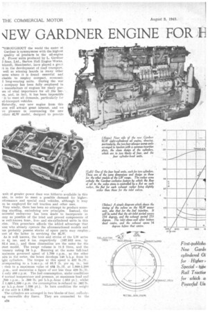
Naturally, any new engine from this irce will attract great interest, and we ve pleasure in announcing the new .rdner 8LW model, designed to provide unit of greater power than was hitherto available in this ake, in order to meet a possible demand for higherrrformance and special road vehicles, although it may so be employed for rail traction and other uses.
Very wisely, there has been no attempt to produce someling startling, embodying nets' principles. Instead, the iccessful endeavour has been made. to incorporate as any as possible of the tried and proved components of re well-known four-, fiveand six-cylindered units in this !ries. This procedure affords the added advantage that lose who already operate the aforementioned models and ins probably possess stocks of spare parts may employ— lost of the latter in servicing the 8LW.
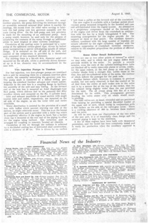
As is well known, the bore and stroke of the LW series re 4i ins. and 6 ins. respectively (107.952 mm. by 52.4 mm.), and these dimensions are the same for the 'test model. The swept volume is 11.2 litres, and the reasury rating 58 h.p. Running at the same full-load raximum governed speed of 1,700 r.p.m., as the other nits in the series, the latest develops 140 b.h.p. from its ight cylinders. The torque at this speed is 432 lb./ft., orresponding to a b.M.e.p. of 95.7 lb. per sq. in., bet rises to a maximum value of 456 lb./ft. at 1,000-1,200 ,p.m., and maintains a figure of not less than 420 lb./ft. t only 400 r.p.m. The fuel consumption. Mader conditions normal temperature and pressure, at maximum load and • J00 r.p.m., is .380 lb. per b.h.p.-hour (.353 pt.), whilst 1,00-1,200 r.p.m. the consumption is:reduced to .362 lb. ter b.h.p.-hour (.336 pt.), In bare condition the weight the unit is 1,936 lb.
The cylinders are arranged in two blocks of four, emlodyng renewable dry liners. They are connected to the
separate crankcase by 20 through bolts. Thw heads are made up as four blocks, each serving two cylinders. . Vertical overhead. valves are 'operated by rockers, the push rods for which are controlled by a camshaft located in the crankca_§e. The weight and overall dimensions have been kept as low as possible consistent with long life and reliability in arduous service. Considerable use is made of light metal, the crankcase and oil sump being in 2L5 alloy.
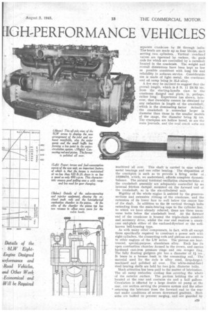
A few may be inclined to suggest that the overall length, which is 5 ft. 11 23/32 his. from the starting-handle claw to the crankcase flanged end plate, is, perhaps, rather long. Experience has shown, however, that durability cannot be obtained by any reduction in length of the crankshaft, which is the dominating factor Actually: the crankshaft is somewhat larger in diameter than those in the smaller models of the range, the diameter being 31 iris. The crankpins are hollow bored, as are the main journals, and the oval crank webs are
machined all over. This shaft is carried in nine white. metal bearings and one roller bearing. The disposition of the crankpins is such as to provide a firing order ot , 15268473, which, we understand, affords complete dynamic balance. The ,natural totsional Oscillation characteristics ot
the crankshaft assembly are' adequately controlled by an internal friction damper mounted on the forward -end of the crankshaft, as in the six-cylindered unit.
Rigidity of the whole engine is assisted by the generous sections and extensive ribbing of the crankcase, and the extension of its lower face to well below the centre line of the shaft. In addition to the 20 vertical through bolts extending from the main-bearing caps to the cylinder feet, to which we have already referred, there are .three trans verse bolts below the crankshaft level. At the forward 'end of the crankcase is housed the triple-chain camshaft and accessory drive, whilst the rear end receives a crankcase end-plate either of the enclosed-flywheel or the wellknown bell-housing type.
As with many other components, in fact. With all except those specifically required to construct a power unit with eight cylinders, the connecting rods and pistons are commoi, to other engines of the LW series. The pistons are heattreated, special,purpose, aluminium alloy. Each has its
open combustion chamber formed in the crown, and carries hardened cast-iron pressure rings and one scraper ring. The fully floating gudgeon pin has a diameter of l, ins It bears in a bronze bush in the connecting rod. The -material used for the reds is alloy steel, drop-forged, machined and polished all over. The white-metal-lined steel bearing shells are held by two Fin. diameter bolts.
Much attention has been paid to the matter of lubrication. The oil sump embodies cooling fins covering the whole of the exterior surface. The portion holding the oil is
located at the rear -and contains six and a half gallons. Circulation is effected by a large double oil pump at the
rear, one section serving the pressure system and the other returning the lubricant from the forward end to the rear end under conditions of severe downward gradient. Both sides are baffled to prevent surging, and -are guarded by filters. The pressure oiling system follows the usual Gardner practice, the pump delivering the lubricant through an accessibly mounted external filter before it reaches the bearings, the excess from the relief valve serving to lubricate the fuel pump cam box governor assembly and the inain timing drive. On the fuelpump cam bok provision 'is made for the mounting of an additional pump. Such a pump would, however, be used only for the purpose of circulating the contents of the sump through an additional cdoler to meet tropical or other extreme conditions.
Circulation of the cooling water is performed by a water pump of the spherical carbon-gland type, driven by helical gears incorporating a special self-aligning spindle of unique design. It is mounted on the off side of the unit, and control of the temperature is provided by a thermostat unit composed of two standard-elements.
For starting there is a 24-volt 6-in, diameter axial tnit mounted on the off side, whilst a positively driven dynamo of up to 8 ins, diameter may be accommodated on the near side.
Two Injection Pumps in Tandem
For fuel injection, two four-plunger pumps are combined into a unit by mounting them on a common insertion plate or cradle, the assembly embodying the governor cam box. The pump shaft is connected to a helical sliding gear forming the standard Gardner advance and retard system. Adjacent to the cam box is a coupling flange to facilitate the assembly of the unit and easy timing. At the forward end of the cam box is mounted an Amal diaphragm-type feed pump, which delivers fuel to the patented fuel filter overflow return unit mounted on the No. 2 cylinder head:
Inlet and exhaust manifolds of round section with single ventral inlet and outlet, respectively, are mounted on the bff side of the engine, as are the water inlet and outlet manifolds.
Water distribution is assisted by the provision of a small box with baffles which prevent starving one side of the system, as might otherwise occur. This box is at the lowest part of the system and is provided with a drain tap which . is completely effective if the engine be level,-but a further drain tap is mounted at the rear end of the piping to allow tor the engine being inclined. The induction pipe is arranged for coupling to remotely 'located air cleaners. Circulation of the air through the radiator is achieved by a six-bladed cooling fan of fabricated steel construction, 1.N ith a diameter of 20 ins. This is driven by an endless
V belt from a pulley at the forward end of the crankshaft.
The new engine is available with a Gardner patent silent vacuum pump mounted integrally in the forward end case and self-lubricated from the engine system. An alternative is a proprietary compressor carried at the -forward end of the engine and driven from the crankshaft in conjunction with the fan by a triple triangulated V belt. The mounting arrangements for the engine provide for its support at three or four points. The excellent dynamic balance, combined with the large number of impulses per minute afforded by the eight cylinders, together with the adequate suppression of crankshaft torsional resonance, reduces to the simplest proportions the problem of efficient. mounting.
Some Other Small Refinements
There are one or two other points of interest-to which' we may refer, and in which the new engine differs from previous models in the series. To provide a smooth exterior, even the nuts of the cylinder-holding-down bolts are blanked off by easily removable plates or covers, whilst, for the same reason, at the fuel pump or near side, the cylinder blocks form a straight line, unlike those in the four, five and six-cylindered units of the series, the contour of which follows the passages for the push rods.
Another feature which, however, is common to previous models, but not easily observed, is that the control of the oil feed from the centre of each rocker arm to the valve end is by a narrow flat at the top of the rocker, that for the exhaust being slightly wider than the one provided for the inlet. The oil creeps along this flat at a rate determined by its width. This .arrangement prevents flooding the valve stems with oil which would result in smoking. The inlet valves are, as usual, shrouded and are prevented from turning by providing a special flat-sided washer atthe .upper end of each, which works in conjunction -with a flat surface on the side of the valve-gear cover.. There is a working clearance of .001 in. between these washers and the cover.
As will be seen from our illustrations of the two side_s _ of the new unit, it is of beautifully clean design and the external piping is kept to' the minimum.
A few of these engines have been built with Ministerial permission,: and the model has been completely tested and is ready for production when the neceAary approval is given.