


Gradual Release Gear for Multi-stroke Brake
Page 34
If you've noticed an error in this article please click here to report it so we can fix it.
A R6ume: of Patent Specifications that Have Recently Been Published THE Neate trailer brake has for many years been successfully marketed as a unit component, and patent No. 522,389 shows an improvement in the design. The patentees are R. Neate, 60-62, London Road, Kingston-on-Thames, and F. Chandler.
The brake operates by winding a cable around a drum, the drum being rotated by successive pulls of a hand lever, and being restrained from returning by a ratchet-and-pawl mechanism. Release was formerly obtained by a " knock-out" device on the pawl, operated by moving the hand lever to its extreme " off " position. With this scheme difficulty was encountered if only a partial release was desired, and the present patent shows a means for achieving this.
In the drawing, the toothed drum is moved by a pawl (2) on the hand lever, a second pawl (3) maintaining its position until another pull is made. Pawl 3 is under the control of a pushbutton on top of the lever (via rod 1, roller 5, and rocking arm 4) and this, according to the specification, permits any desired amount of " come-back " to the drum, which can be instantly locked by releasing the button. The original feature is also retained, the abutment (6) causing the pawl (2) to be knocked out at the end of the stroke.
It seems to us that controlled " come-back " is limited to the travel of the ultimate stroke and that a second " purchase" can be taken only when applying the brake.
SIMPLIFIED CONTROL FOR ELECTRIC" PRAMS"
ACONTROL scheme for light electric vans of the pedestrian-operated type forms the subject of patent No. 521,280 by G. Machray and J. Davey, 110, Abbotsbury Gardens, Eastcote, Middlesex. The improvements lie in the construction of the tiller; this performs the functions of steering, braking and power control., Dealing first with the steering, this works on the " reel-of-cotton " system comprising a drum (1), from which a flexible cable (4) is piped to the stub axles at the front. Steering is accomplished by rocking the tiller, shown end-on at E'to the right or left. The
A32 tiller is also hinged in a fore-and-aft direction, and by letting it fall, the brakes are applied by •a pull-rod (3). Power is controlled by a push-knob on top of the tiller, an interlocking arrangement preventing its use while the brakes are on.
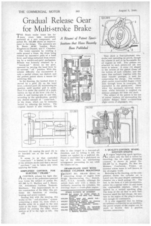
SWASH-PLATE UNIT WITH RUBBER CYLINDER MOUNTINGS
pATENT NO. 520,416 shows an interesting design of engine from Briggs Manufacturing Co., Detroit, Mich., U.S.A. Actually, although the patent deals only with a means for resiliently mounting the cylinders, the drawings depict a swash-plate engine.
They show a four-cylindered twostroke unit operating on petrol, though the scheme is said to be favourable for oil engines as well. Two pistons are attached to each piston-rod (3) and move in unison. A cover (1) shaped to the reverse of the piston closes off the botton of each cylinder, and the space thus enclosed, together with the usual transfer passages, is used for compressing the charge. The wobbleplate carries round-ended fingers which slide through bores in cross-pins (2) journalled in the piston-rods. These allow the necessary universal movement, whilst lubricant is supplied via internal passages fed from the shaft.
The subject of the patent is the use of rubber washers (4) surrounding the cylinder flanges; these accommodate slight errors of alignment, etc.
A QUALITY-CONTROL SPARKIGNITION ENGINE AN engine 'employing spark ignition, in which only the fuel is varied by throttling, the air supply remaining constant, is shown in patent No. 520,597 by A. Bagnulo, 73, Rue des Minimes, Courbevoie, France, an inventor whose name is well known in the oil-engine world.
Referring to the drawing, on the compression. stroke the cylinder air is forced into the pear-shaped combustion chamber via a small passage (2). The fuel, in the form of a rich air-emulsion, enters via a special valve (1) and forms the combustible mixture, which is ignited by a normal sparking plug. The form of the au i flow is such that, however small the fuel charge, the mixture in the region of the plug is always rich enough for combustion.
It is also suggested that by fitting an ordinary carburetter as an auxiliary, the power output of-the engine can be made so flexible that a gearbox becomes unnecessary.