


A New Fuel-injection System
Page 74
If you've noticed an error in this article please click here to report it so we can fix it.
A FUEL-SUPPLY system haVing A Résumé of Patent Specificaseveral novel features is disclosed by Continental Motors Corporation. tions That Have Recently Been Detroit, Mithigan, U.S.A., in patent Detroit, Mithigan, U.S.A., in patent
No. 443,015. Whereas in the usual system the injection pump has a separate unit per cylinder, and each nozzle valve is operated by the
A.singlecylindered injection pump is used; this produces a pulsating pressure in a pipeline common to all four cylinders. Each injeetor has a normal pressure-opened needle valve, but the closing pressure --apart from alight spring (1)—is supplied by an outside spring (3), yin the medium of a rocker arm. This large spring is sufficient to resist even the injection pressure, and injection does not occur until the spring is compressed by a pull-rod (2) operated by a timed eccentric. . The sequence of operations is as fol.lowsi—The single-cylindered pump produces a rise of pressure in the, common line, and injection occurs in the particular cylinder in which the nozzle spring is unloaded by its rocker. When the fuel pressure falls.' however, the nozzle valve is closed automatically by its spring (1) and injection terminates.
Minimizing Nozzle Leakage.
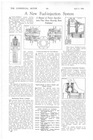
rrO prevent undue fuel leakage past
the valve stem is 'the object of the &sign shown in patent No. 442,899, by E. F. Veglid, 37, via Pelvo, Turin, Referring to the accompanying drawing; the plunger (2) is perfectly fiat on the end, and forms the vabie member in conjunction with the flat'seating washer (5). The fuel is fed through bore 1 into an annular groove (6), Whence it paSses via bore 4 into a second groove (3) under the seat of the .plunger.. The pressure of the fuel lifts the plunger, and discharges the central nozzle. The claim for minimized leakage is based on the fact that when the valve is seating there is a complete cut-off of pressure ; this means that the plunger need not be made exceptionally accurate in its fit in the barrel.
c52
ADESIGN of universally jointed hub stated to be specially suitable for twin-wheeled heavy vehicles is shown in patent No. 443,062 by A. Alessi-Grimaldi, 5, Rue Auguste-Beau, Courbevole, France. In the drawing, the axle end carries a spherical member (6) which is bored at four points to accommodate pins (2). Fitting the 'outside of the ball is an oscillating member (5) having a cylindrical end which can move vertically between two plane surfaces (shown in dotted lines at 4). Member 5 carries, by means of bolts (7), the outer huh upon which the Amin wheels are Mounted. Part 1 carries the brake drum and does not oscillate, being located by bearings (n) at one end, and fitting the spherical oscillating member at the other.
• Improvements in Servo Clutch and • Brake Control.
DtkTENT No. 442,735 deals with 1 vehicles in which both brakes and clutch are suction-operated, and discloses improvements in the methods of co-ordinating the action. The patentee, Mavbach-Motorenbau G.m.b.H., of Friedrichshafen, Germany, states that when a suction-operated clutch is withdrawn by the act of releasing the accelerator pedal the vehicle automatically runs free of the engine. This may sometimes be an advantage, but not when heavy braking is necessary and the engine friction ' could be of assistance.
The specification proceeds to describe a system -of control valves by which the heavy application of the brakes automatically re.engages the clutch if this be in. the free position. Moreover, if the brake be released, the clutch does not become free again' until after the accelerator pedal has been once again depressed, thus retaining the retarding effect of the engine.
A Continental Combustion Chamber.
FROM Limited Company (formerly Skoda-werke) of Plzen, Czechoslovakia, comes, in patent No. 442,340, a design of combustion chamber for oil engines. The object of the scheme is to nermit the chamber itself to reach a high temperature. while keening the injection nozzle in a water-cooled state. The former condition is attained by forming a large number of channels on the exterior of the combustion chainbet ; this ensures that, whilst the actual --area of contact is small, a good mechanical fit is assured, and the chamber is well able to withstand the stress of the power stroke. The chamber is made of metal having a low conductivity, such as constantan or, tungsten steel. To keep the temperature of-the injector at a sufficiently low value, it is placed in a copper shroud (1), which has water passages around the outer periphery.
There are similar channels to insulate from heat the copper shroud around the injector.