


LATHE GADGETS.
Page 31
If you've noticed an error in this article please click here to report it so we can fix it.
Some Useful Fittings Described by Our Driver and Mechanic Readers.
THE prize of 15s. is awarded this week to " H.A.B.," of Rotherham, for his interesting description of an ingenious but simple indicator fitting for a lathe. It is most useful in connection with a screw-cutting job, but is not, of course, confined to that purpose. Its chief advantage is that it entirely does away with the need for chalk, the timehonoured material for marking the prop;ress of a screw-cutting job on a lathe.
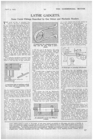
Fig. 1 of one of the accompanying illustrations shows the shape of this indicator as it is first cut from a sheet of 1-16-in, metal, either steel or brass, but preferably the latter, if it can be obtained. There are no dimensions given, but the length must be such that the indicator will clip round the boss. of the feed wheel, and fasten on the underside by one -k-in. bolt, in the same way as a hose clip of the old-fashioned type is fastened on to the hose. The holes shown at the end of the indicator are clearance holes for a 4-in, bolt for that
purpose. '
The indicator should be secured to the boss of the feed wheel in such a way that whilst it will not slip, it may, neverthe
less, be turned round by hand, so that it may be adjusted, for any job, to stand opposite a mark which should be made, by means of a file, on the projecting boss of the carriage which is contact with the boss of the feed wheel; as shown on the sketch.
The peculiar looking tool which is shown on another of our illustrations is said, by " A.E.T.," of Holborn, London, to be very useful for cleaning out turnings and similar obstructions from the interior of the nose of the lathe chuck. It is made from steel rod, about 3-16 in. or 4 in. diameter, and about 30 ins. long. The raw material (the rod) should be heated in the middle for a length of about 6 ins. or 8 ins. to a bright red, and then given a double turn round a piece of 2-in, bar, as shown. Then heat the ends and turn outwards at right-angles, the
projections being no more than in. long. The next operation is to grind or file the end to 55 degrees, the same angle as a Whitworth thread. Back off the points of the tool, as shown, in opposite directions, and harden them.
Another useful lathe fitting is described by " C.G.," of Chorley. It often happens, he says, that when an urgent repair job comes in, and the lathe is approached to do its share of the work, it is found that a carrier of the proper size to do the job is not available. Now an adjustable carrier is eaSily and cheaply made, as shown in the accompanying sketch, and certainly saves its cost many tithes over in a very short time.
It is made from a length of bar steel of fin, square section. The length should be about 15' ins., and it should be turned at the ends,' as shown, for a length of 14 ins, and then cat in two. Two holes are bored in each half, one of them being 4 in. diameter and the other. for 7-16-in. Whitworth tap. Take particular care to note that the halves of the carrier are exactly alike, so that there is one clearance hole and one tap Ping hole in each ; do not make the mis take of putting the two clearance holes in one part and the tapping holes in the other.
The screws are 7-16 in. Whitworth, and should be turned specially from fin. bar stock. They are 3 ins, long under the head, and the tommy. holes in the round heads are 5-16 in. diameter. The screws will last much longer if they are ease-hardened before they are put to use.
Clamp the two parts together, and
cut a -4-in, square hole in the centre to assist the carrier to grip strongly.
" 11:A.B.," of Rotherham, is of opinion that most of the grinding attachments which have hitherto been described on this page have been rather too elaborate, or too costly, for the ordinary garage hand to bother with, and he sends a suggestion of his own which, presumably; has no such drawbacks. At any rate, he says that he made such an attachment from spares and scrap parts.
Apparently the attachment was originally made in order to help " H.A.137" to get out of a nasty job of filing a number of shafts. The, grinder, as shown on the sketch, will do very well for this purpose, and also for internal grinding.
The drive for the grinding wheel, which, as may be seen from the sketch, is fitted to a spindle on the slide rest, is from a special shaft whioh is mounted on the side of the lathe. It has a small belt pulley fixed on it, in line with the largest pulley on the speed cone of the lathe, the ratio of the two being 8 to 1. This shaft is located.at one end by the two collars shown, and has a keyway cut throughout its entire length, so that the V pulley which transmits the drive to the grinding wheel may be -shifted from end to end.
The grinding wheel is 6 ins, in diameter and 14 ins. wide. The feed is 3-1,008ths of an inch. It is important that provision be made for an ample supply of water to the atone while it is in use. A leather belt is used for the preliminary drive from the speed cone of the lathe; that on the grooved pulleys is a rubber-covered wire. It will be found an improvement, to fit a jockey pulley to take up the slack in the wire.
The following dimensions relate to File equipment which " H.A.B." fitted; they are not arbitrary, but may be useful as a guide to other readers.
The diameter of the large pulley on the lathe cone is 2 ft., the small pulley being 3 ins.. The V-grooved pulley on the shaft is 3 ins, in diameter, and the corresponding pulley on the grinding wheel is 2 ins, in diameter, making this ratio 4 to 1, and the total reduction, from the speed cone to the wheel, 32 to 1.