


Hydraulic Governing of Injection Pumps
Page 52
If you've noticed an error in this article please click here to report it so we can fix it.
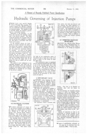
FROM C.A.V., Ltd. and W NicolIs, both of Warple Way, London, W.3, comes, in patent No. 589,722, a description of a hydraulic means for governing an injection pump. The scheme is said to provide stable, yet sensitive, governing in a convenient manner.
Referring to the drawing, 1 is the lever that con:rols the injection output and 2 the driver's control. The latter varies the position of a by-pass valve (3) and the spring force applied to a piston (4); this piston is provided with leakbores in its crown.
In the position shown oil from a pump (5) passes through the holes in the piston and reaches a second piston (6), which is moved in a direction that sets the pump for maximum delivery for starting. As soon as the engine runs, the increased oil pressure lifts the first piston and opens a valve (7). This permits the oil to reach a variable choke (8), which is worked by the movement of the output control arm; the oil can also reach the upper side of the piston (6) and so cancel out its onesided force.
This piston is now subjected to two opposing pressures, one from the oil pump and another from the restriction caused by the choke, so that a state of equilibrium is attained for all settings of the driver's control.
ALL-MACHINED CYLINDER HEAD
TO ensure uniformity of output of the several cylinders of an engine is the object of a scheme shown in patent No. 589,842 by C. Hill and Aston Martin, Ltd., Victoria Road, Feltham, Middlesex. The chief feature of the head is that none of the surfaces is left in the cast condition, all being machined.
The drawing shows a section of a cylinder with the improved head in position. •The inlet valve (I) is positioned vertically, and lies well within the cylinder bore. The exhaust valve (2) is set at an angle and seats within a wedgeshaped recess (3). This recess forms the bulk of toe combustion space, as the piston rises so high that it has to be given a recess in the crown to clear the inlet valve.
The combustion space is machined out by a dovetail-shaped end mill, which is set at the required angle, but is fed in on an axis parallel to the bore of the cylinder. The patent covers also this method of machining the recess. A feature of the layout is the excellent cooling afforded to the exhaust valve, because of its proximity to the water spaces (4 and 5).
A NEW ROTARY VALVE A ROTARY valve, forming the sub ject of patent No. 588,746, from F. Swain, 41, Amberley Gardens, Stoneleigh, Ewell, Surrey, outlines a design which balances out the thrust caused by compression and combustion.
The valve (1), spherical ifs outline, is rotated by a spindle (2) driven by external timing gears. The ports (3) in the valve, contacting the cylinder, form the main combustion space. The head is parted across its largest diameter, to permit assembly, an oil-duct (4) being machined in this plane. Oil fed through a pipe (5) is returned by pipe 6, so that a circulation is established.
The stationary head is formed with four ports, two inlet (as shown) and two exhaust, the valve rotating at a quarter engine speed in the case of a four-stroke. The projected area of the two ports in the valve is arranged to be a little less than the area of the cylinder entrance, so that only a slight axial thrust is created. This is sufficient to maintain a good seal without creating undue friction.
AN IMPROVED MAGNETIC BRAKE SHOE
PATENT No. 589,737, from Warner Electric Brake Manufacturing Co., South Beloit, Indiana, U.S.A., shows a modification to the design of magnetic
brakes. The aim is to produce an assembly that will be silent in operation.
In the drawing, the magnetic element is seen at 1; this is an annular " pot " containing a coil of wire, and forms the stationary member of the brakes. It is recessed to receive an inlaid ring of nonmagnetic friction material (2).
• The rotary part comprises an arni.sture ring (3) built up from a number of plates arranged edge to edge and welded on to a non-magnetic ring (4). The non-magnetic ring is attached to the hub Range (5) by means of numerous spring blades (6), which maintain a light rubbing contact even when in the " off " position.
Silence of operation is said to be attributable to recesses formed in the adjacent edges of the armature plates, so as to increase their rigidity and put their vibration frequency beyond the audible limit.