


REVERSING GEAR FOR A STEAM WAGON.
Page 34
If you've noticed an error in this article please click here to report it so we can fix it.
A Résumé of Recently Published Patents.
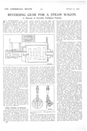
AN INTERESTING and simple device, designed to afford a powerful reversing gear at slow speed, is patented in No. 185,836 by J. Sadler and E. Atkinson., of Preston. On the engine crankshaft, and mounted within the crankcase, is a driving pinion, which meshes with a pair of idle planetary pinions which are carried upon pins secured to the crankcase itself. These
pinions again engage with cogs cut upon the interior of a sleeve which, reduced and extended, passes outside the crankcase along with and surrounding the
crankshaft. On the end of tho sleeve claws are cut which are designed to engage with others upon a sliding sleeve; a similar set of claws is formed upon a short sleeve which is .secured upon the splined end of the crankshaft. The sliding sleeve may be moved so that it engages either with the claws upon the sleeve or with those on the engine shaft; on, its exterior this sleeve is splined, the splines engaging with suitable grooves upon an outer sleeve, to. which is secured the main -driving sprocket of the transmission gear of the wagon. The sliding sleeve is controlled as to its position by one or other of the means usually adopted for this and similar purposes, and it will be gathered that, when the claws upon it are in engagement with those upon the crankshaft, the drive is the forward, direct, and high-speed one. When these claws are in engagement -with those upon the extended sleeve of the outer wheel of the epieyelic gear, the drive is reversed and is much slower than the normal, the exact ratio depending, of course, upon the proportion to the gearwheel employed.
Other Patents of Interest.
An interesting and novel device for indicating the level of the fuel in a tank, or for allied purposes. is described in specification No. 185,840, by G. Constantinesco. It can best be described by reference to the accemeanying drawings, which show the device itself, X being the hole whereby communication is established between this fitting and the tank. the connecting means being a pipe, which.
B50 •
passes vertically into the tank and reaches almost to the bottom of it. Referring now more particularly to the illustrations, the central tube is the sight glass, the outer one being merely a support and II protection. The upper end of this tube, it will be noted, is open to the atmosphere by means of a fine hole in the screw cap. Its lower end dips into a quantity of coloured liquid held in
small chamber, which preferably should be about half full. It should be noted that the hole to which we have already referred opens into the upper part of this chamber, which is, therefore, in direct communication with the fuel tank in the way we have described. In the chamber there is a small, curved-metal diaphragm, in which small holes are drilled below the liquid level. A -rubber diaphragm is clamped by its edges to the metal diaphragm, and the two are separated by a spring; the rubber one, however, may be actuated by a movement of the small press-button shown. The operation is as follows :
With the diaphragms in the positions shown the level of the liquid in the main pipe corresponds with that in the tank; the level of the coloured liquid in the chamber is the same as that in the indicating tube, as appears in the sketches. By pressing the button the rubber diaphragm can be forced into almost close contact with the steel one, and while so held a. steady pressure is maintained in the clamber. The pressure in the chairiber forces the coloured liquid up the inside of the indicator tube, and at the same time depresses that ir the tube in the petrol tank; as a rule bu ibles will escape into the petrol tank until a state of equilibrium IS established, chile the rubber diaphragm is held firm .y against the metal one. When this oecurs, the height of the column in the indicator tube will remain steady an suitably calibrated, will indicate the 1, eel inside the tank.
A combination hydraulic anu iechanical valve tappet is described y J. M. Norman in specification No. 1,893; the tappet is in two parts, both cylindrical and one sliding within the °Leer. Communication is established between the space between them and the engine-oil pump, so that a supply of oil under pressure is delivered to act as a buffer between the two of them, during the time that the tappet is in its lower and idle position; operation of the lappet by the cam takes place while the oil is there, so that it acts as a buffer, taking up all clearance. While the tappet is working, a little of this oil is allowed to escape, thus providing a clearance, which 'is essential to the proper closing of the valve. II is worthy of note that the regular replenishment of this oil supply, after every operation of the valve, suffices to provide for differences which may arise in relative lengths of tappet and cylinder due to heat.
T. H. Parker, in No. 185,590, refers to a previous invention in his patent No: 162.527, in which the engine is built up with a cylinder and a crankcase in one, side plates being employed for the latter to enclose it and to provide bearings forthe crankshaft. In the present specification he describes how the same principle may he used in connection with the manufacture of multi-cylinder engines.
Specification Ni). 185,822, by RudgeWhitworth, Ltd., refers to the fitting of detachable wheels to existing hubs. The patentees refer to a prior specification (No. 185,190), in which they describe a detachable wheel construction ; they point out that detaxihable wheels are preferably constructed in only a few standard sizes, and that, when it is desired to fit these sizes to existing hubs, it is objectionable to haveito depart from standard. This particular specification describes several practical methods of avoiding this departure from standard.
An epicyclic change-speed' gear, complete with disc clutch and operating gear, is in the construction described by T. E. C. Hurst., in No. 185,820, embodied in the rear axle casing. An interesting feature is the clutch-operating gear. which includes a rod which is disposed along the inside of the worm shaft. The suspension which is described by W. IL Wood, in No. 185,802, is rather interesting; there are two springs of the transverse type, located one above and one below the wheel centre ; at their ends these springs are coupled by universal joints to spiders, which themselves support the wheel hubs and bearings.