


ELECTRICS FROM A PETROL VEHICLE• FACTORY
Page 12
Page 13
If you've noticed an error in this article please click here to report it so we can fix it.
J. and E. Hall, Ltd., of Dartford, produce 4 and 5-ton Battery ElectricVehicles Designed for Heavy-duty Wok and Embodying Several Novel Features.
MANY users of commercial vehicles will be -surprised and interested to learn that those well-known builders of chain-driven vehicles, J. and E. Hall, Ltd.,. of Dartford, are turning their attention to the production of two battory-electric vehicles, one designed to carry -4 tons and the other 5 tons. Although few pecple. realize the fact,
it is not the first time that this company have produced such machines, or others in which electricity played its part ; for, as a matter of fort, the first Tilling-Stevens petrol-electric vehicles were built by them, and in 1909 they built some eight battery electric vehicles, most of which were supplied to the Brighton Bus Co., by whom they were employed on passenger service for many years, and, although they were eventually sold, we believe that some of these vehicles are still in active operation. They were chain driven, and the single driving motor of each was situated at the rear, and these features of design have been retained in the two models just produced.
So far as possible, the standard units and parts embodied in the 4 and 5-ton petrol vehicles have been utilized in the new el ectrics, and this without sacrificing accessibility and even-weight distribution in any way.
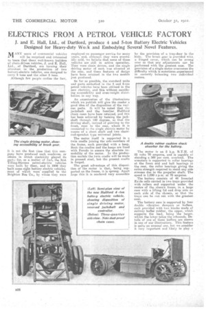
An examination of the illustrations which we publish will give the reader is good idea of the disposition of the various parts. It will be noted that the jackshaft and the familiar Hallford chain cases have been retained, and this has been achieved by turning the jackshaft through 180 degrees, so that the driving shaft, instead of pointing to the front, Tuns to the rear, where it is connected to the single electric motor by means of a Alert shaft and two chair'. nod-sprocket type universal joints.
The motor itself is supported in a twin cradle joining the side-members of the frame, each provided with a keep. Both the cradles and the keeps are lined with Ferodo to ensure the absolute immobility of the motor. In the production models the twin cradle will be made in pressed steel, but the present credie is forged.
The groat advantage of this disposition of the motor is that,. being supported on the frame, it is sprung. Apart froin this it is rendered very accessible
by the provision of a trap-door in the body. The brush gear is provided with, a -hinged cover, which can be swung over so that any adjustments can be performed with the greatest ease. The provision of is single motor overcomes the difficulty which is sometimes experienced in correctly balancing two individual motors.
The motor is an 8 h.p. B.T.H. of 85 volts 70 amperes, and is capable of standing a 300 per cent. overload. The armature is supported in roller bearings at the front and and ball bearings at the rear, the roller bearings giving the extra strength required to resist any side stresses due to the propeller shaft. The speed is 1,050 r.p.m. at 70 amperes.
The battery consists of 44 Ironclad Exide cells carried in two trays provided with rollers and supported under the centpe of the chassis frame, in .a large case with a lifting lid and drop side on each side of the chassis, so that the trays can be run out with the greatest ease.
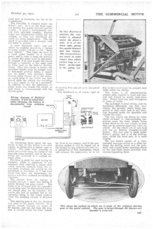
The battery case is supported by four double vibration dampers or buffers. each provided with two blocks made of railway buffer rubber, the upper, which supports the load, being the larger. whilst the lower takes the rebouuds. Details of one of these buffers are shown in one of our illustrations. This feature is quite an unusual one, but we consider it very important and likely to play is
great part in increasing the life of the accumulators.
The controller ie situated under the driver's seat. It is of the drum type, and permits five speeds forward and two reverse. it gives a series-parallel control with split-field winding. Electric brake and regenerative control are not utilized, as they are considered not worth the. extra complication. The to speed is provided with a diverter with the fields in parallel.
A most important point, and one which we consider should be a feature or every electric vehicle, is the " deadman control." This takes the form of a small pedal similar to a throttle pedal, and in order to keep the machine in motion this pedal must be depressed. If released, it at once breaks the circuit through a contactor of the same type as those used on the District Railway trains. Once this circuit is broken the controller handle must be brought hack to first-speed position before a restart can be made; this prevents undue stresses being thrown on to the motor, as would occur if the circuit Was completed while the vehicle was travelling ata slow speed, or was at a standstill. In addition to this, the application of either brake also breaks the circuit, as each brake is interconnected. with the cut--out pedal.
An interesting point about the controller is that all the wiring is in solid copper, so strong that it cannot wear or vibrate. The leads from controller to motor are carried along the inside of the near-side frame-member, and at the controller are connected to a marked terminal plate.
Provision is made for road testing by ammeter, which is connected to two terminals after removing a copper strip which normally connects these. No instruments whatever are carried on the dashboard or elsewhere, as it has been found that these are unueceseary, expensive and often rendered unreliable by The current from the battery is brought through a main fuse before it peeks through the plug circuit. The latter is so arranged that the controller circuit plug must be disconnected before the charge plug can be inserted ; this avoids any risk of accident due to the controller being in the wrong position when the charging current is switched on.
The steering gear is also the standard n it used on the petrol vehicles. It is merely turned through an angle of 90 degrees, and therod from the drop arm is carried across the front instead of running fore and aft as in the petrol vehicles.
The dashboard is, of course, right at
the front of the chassis, and in the production models it will he sloped out at the bottom by the addition of a, tool lie-er or something of that description, which will enhance the appearance, as in the
first models constructed the straight dash looks rather too abrupt.
The frame is of channel-section pressed steel, tapered to front and rear, and well braced by sturdy-cress-members. Fitted bolts are used throughout in place of rivets.
The jackshaft is bevel driven, and the bevel-type differential has four starwheels, the sprocket shafts being supported at their outer ends in ball bearings niounted inside the sprockets and outside the tubes.
The rear -wheels are driven by roller chains enclosed in duet-excluding aluminium cases, the chain wheels being bolted direct to the rear wheels, so that they can he renewed separately when re., quired. All the wheels are of cast-steet and run on floating phosphor-bronzd bushes. The rear axle is made under Butler's patent, and is of the built-up type, whilst the front axle is a solid forging,
"The two brakes consist of a footoperated low-type acting on a drum between. the driving motor and the jack. shaft, and a hand brake operating direct on the rear-wheel drums provided with internal-expanding shoes.