


Patents Completed.
Page 24
If you've noticed an error in this article please click here to report it so we can fix it.
Hartridge Tire Syndicate, Ltd., and Another.—No. 26,480, dated 22nd November, 1906.—The tire consists of two sections of rubber (A) mounted, in the usual way, on the rim (B) of the wheel. A floating ring (C) is arranged in the thickness of the tire; this ring is composed of segments, which are secured together by bolts (X), so that any desired amount of pressure can be brought to bear upon the tire, Air-spaces (F) are arranged within the body of the tire; these serve to increase the resiliency.
VARIABLE SPEED GEAR.—Tourtel. —No. 20,127A, dated 20th December, 1906.—This invention relates to speed gears of the type in which a series of spur wheels, fixed on the driven shaft, are in constant mesh with an oppositely arranged series of wheels, loosely mounted on the driving shaft. A portion of the driving shaft (a) is hollowed at al, so as to receive a plunger (f) which is adapted to slide therein. A number of openings (h) are formed in the shaft, each of which contains a ball (g) which normally rests upon the rod (f) of the plunger. These balls can be thrust outwards in the openings (h) by the piston (P) so as to engage either of the wheels (c, d, e), when the rod is moved longitudinally in the shaft (a). It will be seen that, in this way, a variable speed can be obtained.
FRICTION CLUTCHES.—Morris and Others.—No. 21,589, dated 29th September, 1906.—The driving member (1) of the clutch consists of a hollow cone which transmits motion to the driving shaft (11) through the medium of clutch-members (6, 7, 8). The clutch-members are in the form of discs, and their peripheries are cone-shaped. The members (6, 7) are mounted freely on the shaft (11 ), and the member (8) is mounted so as to be free to slide, but not to rotate. Coiled springs (9, 10) are arranged between the clutchmembers (6, 7, 8), the ends of the springs
being secured to the clutch-members by bolts (15). It will be seen that, when the clutch-lever (14b) is so operated as to move the clutch part (8) towards the cone (1), the innermost clutch part (6) is first forced inwards, against the pressure of the spring (18), into engagement with the cone (1), through the medium of the springs (9, 10). As soon as this clutch part is brought into driving connection with the cone, it commences to revolve therewith, and subjects the springs (9, 10) to a torsional strain, with the result that they tend to transmit rotary motion and become shortened in an axial direction, which draws the clutch parts (7, 8) into driving engagement with the cone (1).
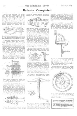
MUDGUARD.—Corsham.—No. 22,220, dated 8th October, 1906.--In order to prevent the splashing caused by the tires
of motor vehicles, a guard (b) is secured to a frame (e) which is loosely mounted on the axle (g); this frame has weights (f) to keep it in the correct position, as shown in the figures. When the guard is not required, the frame (e) may be undamped from the sleeve (i), and turned into a diametrically-opposed position in relation to the wheel of the vehicle, in which position it may be secured by a set-screw (4).
STEERING MECHANISM.—Wheatley.—No. 5,211, dated 4th March, 1907.— The steering wheel is secured to a stub shaft (6) having a pinion (21) integral therewith, the teeth of which engage other pinions (20) which, in turn, engage with the teeth on the stationary steering post (12). The pinions (20) are rotatably mounted on a sleeve (16), the latter being secured to the steering shaft (1). In this way, much less Dower is required to turn the hand wheel than would be necessary if it were secured directly to the steering shaft.
MOTOR BODIES. — Anger. — No. 27,730, dated 5th December, 1906.—ln order to strengthen the body of a motor omnibus, knees (a) extend across the floor (d) of the vehicle and rigidly connect the two sides. The projecting arm (e) of the knee (a) partly supports the seat, and it is connected by bolts (m), which extend through a cast bracket (b), to the side frame (j). Stay rods (f) are provided, to strengthen the overhanging part of the body, at the sides.
SPRING TIRES.—Taylor.—No. 18,753, dated 21st August, 1906.—The tire comprises inner and outer rims (C, D) be
tween which are placed springs (a) in double sets. These springs are U-shaped, and are secured to the inner and outer rims by rivets (b).