


THE FITTING OF TWIN PNEUMATIC TYRES.
Page 66
If you've noticed an error in this article please click here to report it so we can fix it.
A Rdsum4 of Recently Published Patent Specifications.
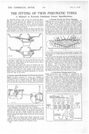
AMEANS whereby either of the rims supporting pneumatic tyres, when used as twins, can be removed, is described in specification No. 281,278, by the Goodyear Tire and Rubber Co., of Akron, U.S.A. One of the advantages claimed is that either rim can be secured or detached by means of screws or bolts, all of which can be operated from the same side of the wheel.
The rim of the wheel is formed so that it provides two conical Beatings, on which the tyre rims rest, the tyre rims being• formed in two parts, as shown, so that the tyre can be released by springing one part of the rim over the edge of the other. These rims are secured to the outer edge cf the wheel by being pressed up the conical part by means of the screws or bolts shown.
The upper view shows the means of securing the tyre rim that is farthest from the operator by means of the long set-screw shown, whilst the lower view shows the means employed for holding the rim nearest to the operator by means of a bolt and ring which presses on the conical part. These means of holding are placed alternately at intervals round the edge of the wheel.
A Change-speed Mechanism for Forward Control.
THE invention described in patent No. 292,650, by HE Motors, Ltd., and G. J. Rackham, is intended especially for use in vehicles where the driver is situated either by the side of or above the engine. The arrangement Is of the ball type, where there is no actual-gate and where
the gearbox is situated some distance behind the driver, the lever, apparently, being operated by the left hand. The right-hand view shows the lever, which has a ball forming a universal fulcrum and a second ball where it joins the lever, which is fixed to a sliding and rocking shaft. The hole in the lever which receives the lower ball is parallel, thus allowing the ball to slide in the hole and work freely although the ratios of the two levers do not coincide in this case.
The rocking and sliding shaft extends rearwards to the gearbox, where it is fitted with a lever which can engage with any of the three selector forks to impart to them the necessary sliding movement for changing gears.
A Plough Tractor for Heavy Haulage.
THE plough tractor described in the specification No.
291,262 of tgo Nardone, of Fondi, Italy, describes a motor plough tractor which is evidently intended for very heavy work. It is of the class of tractor in which a number of blades engage the ground at the same time, thus affording a very firm grip. The main feature of the invention does not lie in the matter of the number of blades engaging the ground at once, but in the manner in which they engage. The specification points out that endless chains which operate blades of the kind have been used before, but in most cases they gradually engaged the ground by travelling down a slope, then travelling along a guide which is parallel with the ground for a certain distance and rising gradually up a slope again.
It will be seen that with such an arrangement the actual distance apqrt of the blades must always be constant, owing to their being connected to the chain at certain distances apart, but, when entering the ground and still on the slope, their distance apart in the ground will be less than when the chain is travelling along a path which is parallel with
the ground. This will cause a great loss of power, as the distance apart of the blades will have to alter while actually in the ground. With the present arrangement there is no part of the guide which is parallel with the ground, the blades descending a slope and rising up a similar slope. The blades can be lifted clear of the ground when required.
A Clutchless Change-speed Gear.
THE change-speed gear described in specification No. 292,178, by L. C. Ord, of London, is claimed to be one that can be worked without a clutch between it and the engine.The necessary disconnection of the engine from the gears is transferred to a hydraulic device, the details of which are not described. We gather, however, that this device is in the nature of what we understand as a differential e•ear ; that it to say, a device containing three elements, in which, whilst one element is held still or is retarded, power is transmitted from one element to a third element In this instance the retarding is effected by means of a pump, the outlet of which can be either partly or entirely closed.
Unfortunately so many of the parts necessary for a clear description are referred to as ':' not shown" that we have to rely on our imagination for much of the detail construction.,