


EQUIPPING A COACH FOR WIRELESS RECEPTION.
Page 14
Page 15
If you've noticed an error in this article please click here to report it so we can fix it.
The Three Different Methods of Coupling High-frequcncy Amplifying Valves and the Method Recommended for a Set Intended for Use on a Motor Coach,
IN THE four articles dealing with this subject and published in recent issues of this journal, we have brought our readers tip. to the point of considering low-frequency amplification or note magnification.. This week we intend to outline the basic principles of high-frequeney amplification.
By high-frequency, or, as it is-also 'called, radiofrequency, . amplification, we denote the method Whereby we employ the three-electrode valve for the purpose of relaying the high-frequency currents, set up in the aerial circuit by ether waves sent out from the transmitting station.
High-frequency amplification is used, as we have already pointed out in a previous 'article, in cases
where the signals received are, from one 'cause or another, too weak to operate the detecting device. It, therefore, follows that it is of the greatest service to ,comperfsate for either distance from the transmitting station or a poor aerial. It also serves to bring in signals from very low-powered transmitters, but; in the case of broad.casting,. this condition does 'not occur, since all the broadcasting .stations----eSpe • eially thosein . Great Britain—are operated on, approximately, the same power, namely. 11kilowatts.
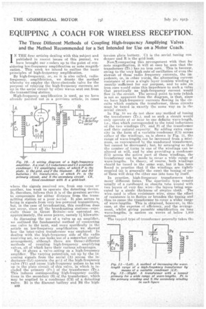
In discussing, the use of a valve as an amplifici, we outlined the fundamental method of connecting one valve to the next; and more' specifically in the article On low-frequency amplification we, showed 'how the inter-valve transformer was employed. In dealing with the high-frequency side of the radio. receiving set, -we can make.use.of a soiriewhat-similar _ arrangement, .although there are threis4. different methods of coupling high-frequency, amplifying valves, all of .which have their various .advantages. Fig. 10 shows a valve..aeting as a. high-frequency amplifier.The varying potentials, set tip by the incoming signals from the aerial (A)'across the-.in.duetance(Li) Operate the.grid of the high-freqneney _valve (V1) and-cause high-frequency pulses to be set up in the plate circuit of this valve, in which is included the primary (Pr.) of the transformer (Tr.). This induces corresponding high-frequency Oscillations in the secondary (S) of the transformer, .which may be applied to a corictenier (C2) Of detecting valve. B1 is the filament .baffery and B2 the high
B30
tensiOn plate battery. el is the aerial, tuning con denser and R is the grid-leak. Now,comparing this arrangement with that for note magnification, it will at once be seen that the transformer (Tr.) has no iron core. This is because, owing, to the very high rate of oscillation of even the ,
slowest of these radio frequency currents, the impedenee, or, in other words, the alternating current
resistance of even a single layerironless winding is
usually.' sufficient for our purpose, and to ado an iron core would raise this inwedence to such a value that practically no high-frequency current would
flow in the circuit. The second Point to note (which is not so apparent. from the diagram, is that, since
we have high-frequency currents flowing in the circuits which contain the transformer, these circuits nmst be turfed in exactly the same way as is the aerial circuit.
In Fig. 10 we do not show any method of tuning the transformer (Tr.), and so such _a 'circuit woidd only operate at or near to one definite Wave-length, i,e., that which corresponded to the total inductance of the two windings (Pr. and 5) of the transformer and their natural capacity: By adding extra capa
city in the form of a variable' condenser(C3) across either of the windings, as is shown in Fig. 11, the range of wave-lengths can be increased from a-mini mum, as represented by the unadorned transformer, but cannot be decreased ; but, by arranging so that
the number of turns in one of the windings can be
altered at will, and by also providing a condenser (C3) across the active part of these windings, the transformer can be made to cover a wide yange of wave-lengths. In theory, of course, -both windings should be tuned in the same way, but it has been found in practice that if the windings are tightly coupled (as is generally the case). the tuning of one of them will drag the other one into tune by itself.
In practice, high-frequency transformers take many different forms. The aperiedie type consist
usually of a cardboard or ebonite tube wound with two layers of very-fine wire—the layers being separated by a single thickness of emPirecloth.. The wire, used is often resistance .wire, since the .effect of resistance is to flatten or broaden the tuning and
thus to pause the transformer to cover a wider range of wave-lengths., This .is, obtained, howeyer,in this case,at the expense of efficiency, And the arrangement, whilSt giving passable amplificatioit on long wave-lengths; is useless on waves of below 1,000 Metres. r
The tapped type of transformer generally takes the
form of an ebonite former with eight slots, the primary aridseeondary being wound in adjacent slots. By means, of a switch, the number of turns in the primary can be varied in font' steps, and a variable condenser provides for fine tuning. This _arrangement is better than the type described above, but it is not sufficiently selective for really first-class results.
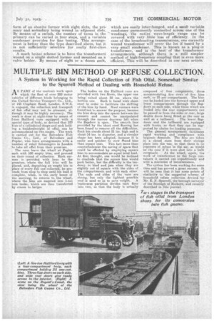
A much better scheme is to have the transformers wound on a single slotted former and mounted on a valve holder. By means of "eight or a 'dozen such,
which are easily interchanged, and a small variable condenser permanently connected across one of the windings-, the entire wave-length range can be covered with very little loss of efficiency. In the ease of the broadcasting transmissions, one correctly Wound transformer will' cover the lot if tuned by a very -.small Condenser. This is know-n as a plug-in transformer, and iS the beSt'. of the transformer arrangements, although there is a still simpler methodof high-frequency coupling that is even more efficient. This will. be described in our next article.