


Water Cooling for Brake Drums
Page 54
If you've noticed an error in this article please click here to report it so we can fix it.
A Résumé of Recently Published Patent Speafica(ions.
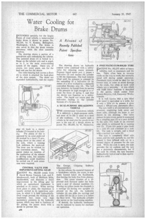
INTENDED specially for the largest 'sizes of road vehicle, a water-cooled brake drum is shown in patent No. 582,264, by V. Kenney, Bellingham, Washington, U.S.A. The brake is also novel in that the drum remains stationary while the shoe assembly revolves.
The drawing shows a .section of a non-driven axle embodying the scheme. The jacketed drum (1) is bolted to a flange on the tubular axle and is piped, as at 2, to the main water-cooling system of the engine. There are, of course, two water pipes, one for the lead and one for the return.
The roller-bearing hub carries a drum (3) to.which is attached the back-plate of the shoe system. The shoes are expanded hydraulically, and the supply pipe (4) leads to a master cylinder (5) located in the hub
eat, The piston of this is operated by an axial push-rod (6) worked by a lever 17) projecting down to the centre of the axle, where a running fork embraces the push-rod. The lever can be worked by any convenient means. The patent makes no mention of the application of the scheme to driving axles, but suitable modifications could doubtless be carried out if such extension were required.
CONTROL VALVE FOR IMPLEMENT-LIFTING GEAR
PATENT No. 582,028 comes from David Brown Tractors, Ltd„ and F. Meadowcroft, both of Meltham Mills, Huddersfield, and discloses a detail improvement in the lifting gear by which an agricultural implement is attached to its tractor. When moving from place to place, the implement is usually carried in its uppermost position, in which it is held hydraulically. Over rough ground, the shaking of the implement may cause very high momentary pressures in the hydraulic system, which may lead to fractures of tha piping; the patent deals with a device to prevent this. The drawing shows •an hydraulic control valve combined with a safetyvalve for releasing excess pressure. Pressure liquid enters port 1, passes a ball-valve (2) and reaches the cylinder to lift the implement. The toad remains lifted until the pressure is released by the unloading of a ball-valve (3) by means of a lever worked by a manually controlled Bowden wire (4). The ball can, however, be forced from its seating if the pressure be high enough.toorcome the force of spring 5, and thus the device can function as a safetyvalve. The liquid can return past the ball-valve leading to the cylinder because of a by-pass (6).
A DUAL-PURPOSE BREAKDOWN VEHICLE
THE conventional breakdown vehicle is definitely a single-purpose outfit, and most of its life is spent in a state
of idle readiness. To enable such a vehicle to be used also for goods transport is the atm of a design shown in patent No. 582,030, by W. Dunkerley, The Garage, Chipping Sodbury, Gloucestershire.
In this scheme the essential feature of a breakdown vehicle, the crane, is normally housed below the floorboards, thus leaving the body free from obstruc
tion. The crane consists of a jib pivoted well forward under the body upon a pair of channel members (1). Moving on rollers inside the channels is a carriage (2) having two uprights (3) pivoted on the job. An hydraulic cylinder (4) can slide the carriage and so either lift the jib or lower it to below the floor level. The hydraulic cylinder also serves as the load-raising member.
If desired, the hydraulic mechanism can be replaced by means for mechanical operation. A PNEUMATIC-CUM-SOLID TYRE
PATENT No. 582,277 refers to heavy vehiclesi such as excavators and the like. These often have to traverse roads on the way to work, but normally stand still during actual operation. Pneumatic tyres would be ideal for the former case, in order to avoid damage to the roads, but when at work solid wheels are a neessity. A tyre which will 'fulfil either funetion is described in the patent, • which comes from Ruston-Bucyfus, Ltd Excavator Works, Lincoln..
It is well known that a tire filled with water is equivalent to ra solid, but if only a little air be present it gives almost a 100-per-cent. pneumatic effect: The tyre itself is of conventional construction, employing both cover and inner. tube, although the latter is not shown in the drawing. The valve (minus its non-return parts) is connected by a coupling pipe (I) to a port drilled in the axle; this leads to an external pipe which is embraced by a running seal (2). From this point a pipe leads to a cock 0) and continues to a tank (4). The tank is airtight, and is fitted with a normal tyre valve (5).
The tyre is completely filled with water, and the tank partially so, and the system is then inflated with air to a normal degree of pressure for the tyre used. While the cock is open, the tank provides the air cushion and the tyre has a pneumatic characteristic, but if the cock be closed, the tyre becomes hydraulically locked and is then equivalent to a solid.