


THE NEV JEN-TUG
Page 38
Page 39
Page 40
If you've noticed an error in this article please click here to report it so we can fix it.
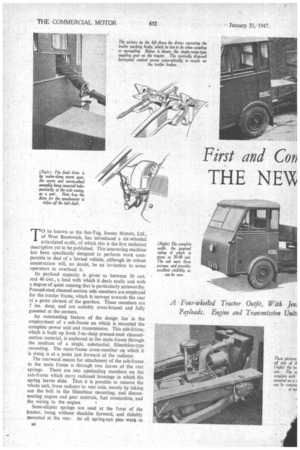
T0 be known as the Jen-Tug, Jensen Motors, Ltd., of West Bromwich, has introduced a six-wheeled articulated outfit, of which this is the first technical description yet to be published. This interesting machine has been specifically designed to perform work comparable to that of a horsed vehicle, although its robust construction will, no doubt, be an invitation to some operators to overload it.
Its payloadcapacity is given as between 30 cwt. and 40 cwt., a load with which it deals easily and with a degree of quiet running that is particularly noteworthy. Pressed-steel channel-section side members are employed for the tractor frame, which is inswept towards the rear at a point abreast of the gearbox. These members are 5 ins deep, and are suitably cross-braced and fully gusseted at the corners.
An outstanding feature of the design lies in the employment of a sub-frame on which is mounted the complete power unit and transmission. This sub-frame, which is built up from 3-in.-deep pressed-steel channelsection material, is anchored to the main .frame through the medium of a single, substantial, Silentbloe-type mounting. The main-frame cross-member on which it is slung is at a point just forward of the radiator.
The rearward means for attachment of the sub-frame to the main frame is through two leaves of the rear springs. There are two upstanding members on the sub-frame which carry radiused housings in which the spring leaves slide. Thus it is possible to remove the whole unit, from radiator to rear axle, merely by taking out the bolt in the Silentbloc mounting, and disconnecting engine and gear controls, fuel connection, and the wiring to the engine. t , Semi-elliptic springs are used at the front of the tractor, being without shackles forward, and slidably mounted at the rear. As all spring-eye pins work in plastic bushes, the problem of lubrication, so far as the suspension is concerned, virtually ceases to exist.
The power unit is a Ford 10 h.p. petrol engine, which gives 30.1 b.h.p. at 4,000 r.p.m., and produces a torque of 46,4 lb./ft. at 2,400 r.p.m. This engine has a bore of 2.5 ins., and a stroke of 3.64 ins., the piston-swept volume thus being 71.55 cubic its.
The cooling water circulates on the thermo-siphon principle, an 11-in, diameter, four-bladed fan, driven by a V-belt, inducing the draught through a large-capacity radiator. The latter is mounted amidships behind the cab, and being thus protected, the cooling water retains its temperature for much longer periods than with an orthodox front-mounted component. Circulation is thermostatically controlled, and air currents through the radiator are induced entirely by the fan, which is suitably shrouded to increase its efficiency.
In order to obtain the necessary electrical output at IR moderate speed, a 4i-in. dynamo is fitted, and is belt
driven, in a triangulated arrangement with the fan. The Solex downdraught carburetter incorporates an atmospheric governor which controls the engine speed to a maximum of 2,750 r.p.m. Petrol is fed to the instrument by a mechanical pump, the petrol tank, of 8i gallons capacity, being mounted forward of the radiator beneath the driving seat.
The gearbox, which is also of Ford make and built as a unit with the engine, provides three forward speeds and a reverse, second and third gears being of the synchromesh type. The basic ratios are 3.40, 1.96 and 1k0 to 1 forward and 4.45 to 1 reverse. With a rearaxle ratio of 11.66 to I, the overall gear ratios are thus 39.68, 22.85 and 11.66 to 1 forWard, and 51.9 to I reverse.
Remote operation of the gearbox is provided by Arens controls, the gear-change leveu . being brought to a position just below the steering wheel, where it comes within convenient reach of the left hand. The drive from the engine to the gearbox is by a single-plate dry clutch, 7.375 ins, diameter, the total friction area being 53.62 sq. ins., with a plate pressure of 450 lb. as a maximum.
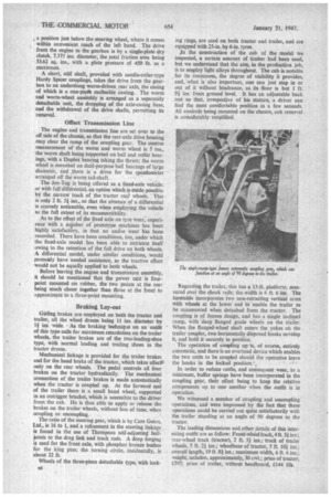
A short, stiff shaft, provided with needle-roller-type Hardy Spicer couplings, takes the drive from the gearbox to an underslung worm-driven rear axle, the casing of which is a one-piece malleable casting. The worm and worm-wheel assembly is arranged as a separately detachable unit, the dropping of the axle-casing base, and the withdrawal of the drive shafts, permitting its removal.
Offset Transmission Line The engine and transmission line are set over to the off side of the chassis, so that the rear-axle drive housing may clear the ramp of the coupling gear. The centres measurement of the worm and worm wheel is 5 ins., the worm shaft being supported on ball and roller bearings, with a Duplex bearing taking the thrust; the worm wheel is mounted on dual-purpose ball bearings of large diameter, and ,there is a drive for the speedometer arranged off the worm tail-shaft.
The Jen-Tug is being offered as a fixed-axle vehicle, or with full differential, an option which is made possible by the narrow track of the tractor rear wheels. This is only 2 ft. 51 ins., so that the absence of .a differential is scarcely noticeable, even when employing the vehicle to the full extent of its manceuvrability.
As to the effect of the fixed axle on tyre wear, experience with a number of prototype machines has been highly satisfactory, in that no undue wear has been recorded. There have been conditions, too, under which the fixed-axle model has been able to extricate itself owing to the retention of the full drive on both wheels. A differential model, under similar conditions, would probably have needed assistance, as the tractive effort would not be equally applied to both wheels.
Before leaving the engine and transmission assembly, it should be mentioned that the power unit is fourpoint mounted on rubber, the two points at the rear being much closer together than those at the front to approximate to a three-point mounting.
Braking Lay-out Girling brakes are employed on both the tractor and trailer, all the wheel drums being 11 ins, diameter by If ins wide. • As the braking technique on an outfit of this type calls for maximum retardation on the trailer wheels, the trailer brakes are of the two-leading-shoe type, with normal leading and trailing shoes in the tractor drums.
Mechanical linkage is provided for the trailer brakes and for the hand brake of the tractors which takes effect" only on the rear wheels. The pedal controls all four brakes on the tractor hydraulically. The mechanical connection of the trailer brakes is made automatically when the tractor is coupled up. At the forward end of the trailer there is a small hand wheel, supported in an outrigger bracket, which is accessible to the driver from the cab. He is thus able to apply or release the brakes on the trailer wheels, without loss of time, when coupling or uncoupling.
The ratio of the steering gear, which is by Cam Gears, Ltd., is 16 to 1, and,a refinement in the steering linkage. is found in the use of Thompson self-adjusting titanjoints to the drag link and track rods. A drop forging is used for the front axle, with phosphor bronze bushes for the king pins; the turning .circle, incidentally, is about 22 ft.
Wheels of the three-piece detachable type, with lock136 ing rings, are used on both tractor and trailer, and are equipped with 254n. by 6-in. tyres.
In the construction of the cab of the model we inspected, a certain amount of timber had been used, but we understand that the aim, in the production job, is to employ light alloys throughout. The cab is notable for its roominess, the degree of visibility it provides, and, what is also important, one can just step in or out of it without hindrance, as its floor is but 1 ft. 9i ins, from ground level. It has an adjustable back rest so that, irrespective of his stature, a driver can find the most comfortable position in a few seconds. All controls being mounted on the chassis, cab removal is considerably, simplified.
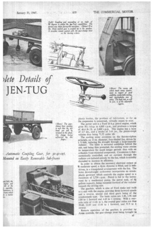
Regarding the trailer, this has a 13-ft. platform; measured over the chock rails; the width is 6 ft. 6 ins. The turntable incorporates two non-retracting vertical arms with wheels at the lower end to enable the trailer to he manceuvred when detached from the tractor. The coupling is of Jensen design, and has a single inclined ramp, with deep flanged guide wheels on the trailer. When the flanged-wheel shaft enters the yokes on the trailer coupler, two horizontally disposed hooks envelop it, and hold it securely in position.
The operation of coupling up -is, of course, entirely automatic, and there is an overload device which enables the two units to be coupled should the operative leave the hooks in the locked positions
In order to reduce rattle, and consequent wear, to a minimum, buffer springs have been incorporated in the coupling gear, their effect being to keep the relative components up to one another when the outfit is in operation.
We witnessed a number of coupling and uncoupling operations, and were impressed by the fact that these operations could be carried out quite satisfactorily with the trailer standing at an angle of 90 degrees to the tractor.
The leading dimensions and other details of this interesting outfit are as follow: Front-wheel track,4ft.31 ins.; rear-wheel track (tractor), 2 ft. 51 ins.; track of trailer wheels. 5 ft. 2-1 ins.; wheelbase of tractor, 5 ft. 101 ins.; overall length, 19 ft. 81 ins.; maximum width, 6 ft. 6 ins.: weight, unladen, approximately, 30 cwt.; price of tractor, .E395; price of trailer, without headboard, £144 10s.