


THE FOWLER LC. TRACTION ENGINE.
Page 36
If you've noticed an error in this article please click here to report it so we can fix it.
A Resume of Recently Published Patents.
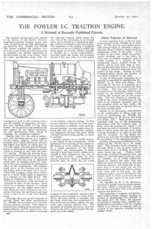
The general arrangement and certain of the details of the Fowler internalcombustion-engined traction engine and cable ploughing set are fully disclosed in specifications Nos. 173,196 and 173,066 The former explains the peculiar construction of the frame and sub-frame, and in particular the flexible suspension of the sub-frame on the main frame, while the other specification deals with the
t •ammiissiou gear to the winding driun, and the method of supporting the gearbox and winding drum on the main frame. As the gearbox also seeves as the rear support for the engine sub-frame, the two specifications must, almost of necessity, be considered together. Dealing first with the engine suspension, the sub-frame serves as a support for the engine, radiator, clutch, and an epieyelie gear which intervenes between the engine and clutch, to which gear we will refer again. The rear end of this subframe is mounted on a spherical seating, which is formed in one with the gearbox casting. Within the bearing is arranged the universal joint through which the power is transmitted to the gears in the box, so that any lack of alignment which may be brought about by warping of the main frame has no detrimental effect on the transmission. The radiator itself • serves as the forward end of the sub-frame, and at its front end it is provided with a spigot, which takes a bearing in a block which again is supported in a bracket on the main frame. The spigot is designed so that it can move laterally in the block, while the block is arranged in slides in the bracket, which allow of a certain amount of vertical movement. As the spigot itself naturally allows of rotary movement the connectkai between the sub-frame and main Frame is seen to be of the most flexible order.
Although there are several features of interest about the other specification, No. 173,056, the principal one is the connection between gearbox, with which is included the winding drum and the transmission thereto, and the main frame. The front end of the box, to which is attached 836 the spherical bearing which takes the rear end of the sub-frame, is of circular form, and is bolted to a substantial casting, which is mounted on the main frame. The underside of the casting is designed so that it serves as a facing to which the drum spigot is secured; further security is afforded by a strong cross-member, mounted under the frame, and arranged se that it fits, as a yoke, on to the spigot on the gearbox support casting. In this manner effective support for both gearbox and drum is obtained, and, more important perhaps, accurate registration between the two, and, therefore, continuous alignment between the gears which transmit the drive from gearbox to drum is ensured.
Another feature, as we briefly stated, is the detail of the transmission, which permits of the reversing of the motion of the drum, or of the vehicle on all gears, by a single movement of one lever. Ordinarily, the transmission is taken through a multi-disc clutch, which is arranged a little distance to the rear of the engine flywheel. Inside the lastnamed component there is mounted an epicyclic gear, of which the sun wheel
is keyed to the crankshaft, and the outer planetary gear secured to a brake drum. 1,7+Theri the main elatch is engaged, and the brake drum free, the transmission is that of the normal motor vehicle, the epicyclic gear running entirely free. The operation of braking the drum, however, reverses the drive, since it puts the epicyclic gear into action.
Other Patents of Interest.
A most ingenious form of flexible joint is the subject of No. 173,026, by R. Chil ton. To the end of each shaft—driver
and driven—there is attached a flange. Between them is fitted a single built-up
component, which is the joint. It is formed of two hubs, which are permanently attached, one to the other, by three sets of flexible members, each of
which consists of a number of thin• spring-steel plates, bedded closely to
gether, and so bent that when in posi tion on the joint they form a V, the apex of which is directed outwards from the centres of the shafts. Flexion of these V-shaped plates affords the freedom of movement required in the joint.
A typo of three-point suspension for a gearbox is described in specification No. 151,617, by K. Graf and others. The fore part of the box is supported in a normal manner at two points on the chas sis frame. The rear end, however, is mounted in a ball bearing, which is supported by the spherical bracket which receives the forward end of the torque
tube. The ball bearing is actually applied to the outer circumference of the
boss of the foremost universal joint of the propeller shaft, so that, really, the gearbox is supported, at its rear end, on its main driving shaft.
Details of an interesting improvement in the construction of lifting jacks are given in specification No. 173,109, the
patentees being A, D. Powell and Lake and Elliot, Ltd. Most people are ac
quainted with one of the outstanding annoyances with the ordinary jack, in that, once the purpose for which a car has been elevated is attained, it is neces sary to crawl under the car, or at least to grope beneath it, in order to reset the jack for lowering. In this design the pawl is set and reset for either operation by movement of the operating handle.
Another lifting jack modification is the subject of No. 173,144, by A. W. Chap
man. This inventor draws attention to the risk which is run, in many forms of screw jack, of over winding, so that the, screw leaves the nut. Chains which have been employed to prevent this, are either so weak that they break at a critical moment, or, if made sufficiently strong to restrain the jack, they are likely to cause trouble awing to the fact that the operator, not being able to per ceive that it is the chain, and not the load which is opposing his efforts, strains some other part of the jack. In this patented design a stop is mounted on the handle itself, so that it prevents its use after a certain travel of the jack screw has occurred.
No. 152,022, by M. 3. B. Barbarou, describes a simple form of clutch-operating gear, which is particularly suitable for use in connection with unit mounted engines and gearboxes. The balancing of engines, and particularly single-cylinder engines, receives at tention in specification No. 154,542, at
the hands of 0. W. Huh. He proposes to arrange a rotating mass, suitably pro
portioned in accordance with the weights which it is desired to balance, and revolving in the opposite direction to the engine shaft.