


A Duat-purpose Engine-oil Filter
Page 36
If you've noticed an error in this article please click here to report it so we can fix it.
A. Résumé of Patent Specifications that Have Recently Been Published
A DESIGN for an oil filter, which
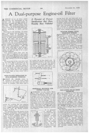
combines the advantages of the full-flow and the by-pass types, is described in patent No. 556,771, by P. Halstead, 236a, Latirmer Court, London, W.6. The device partly filters the whole of the oil, at the same time completely purifying a small portion thereof.
Referring to the drawing, oil enters pipe 1 and passes into an upper compartment, where it permeates the primary filter pack (6) consistingof felt, gauze, or other coarse material. After passing this filter, the oil descends, through a central space,to the outside chamber of the lower compartment. Here it enters the second filter unit (5), ,which consisfs of cotton-wool impreg nated with ethanolamine: But this filter deals with only a small proportion of the total flow, most_of which makes its exit via pipe 3 in a semicleaned condition.
That portion which does pass the Tower filter is collected in the central space and enters tlie bore of the hollow bolt, finally emerging from port 4 in the exit plug, whence it is led to the engine sump.
The proportion of the total dealt with by the lower fdter is governed by the size Of a small restricting bore in the exit plug (4). Another feature is• the provision of a spring-loaded safety valve (2) which can open and shortcircuit the whole filter if the preisure be unduly high, as may occur with a cold engine.
TWIN-CLUTCH OPERATION IN DUAL-ENGINED VEHICLES
pATENT 14. 556,650 refers to vehicles in which the front wheels are driven by one engine and the rear wheels by another, and deals with a
means for working the two clutches from a common pedal. The patentees are L. Jagger and Garner Mobile Equipment Co., Ltd., 82, Wesley Avenue, London, N.W.10.
The drawing shows the layout of the suggested mechanism, which comprises a pedal-operated master cylinder 2) piped to slave cylinders (1 and 3), which operate the clutch arms. To ensure complete engagement, it is necessary that the pistons of the slave cylinders move into a completely clear position, leaving about in. play, for safety's sake. This is done by arranging•the front end of the piston rod to be mounted on a free arm (4) pivoted at a point (5) on the clutch arm. In the retracted position, the setscrews (6) are adjusted so as to give the desired clearance. The hydraulic cylinders (1 and 3) are provided with their own retracting springs, so that they do not have to rely on the clutch springs.
SPHERICAL SEATINGS FOR POPPET VALVES
ACCORDING to the Austin Motor Co., Ltd., and H. Charles, both of Northfield, Birmingham, the usual type of poppet valve is inclined, after some wear has occurred in its guide, to make contact on one side only when it first descends on to its -seating. It then rocks over, to the other side, filially settling down after a few sideways oscillations. This leads to leakage, wear and noises, and patent No. 556,778 shows an improved design claimed to abolish these defects.
It is proposed to provide -t h e valve head arid the seating with spherical mating surfaces, so that lateral errors in seating do no t affect the sealing action In the drawing, which is dimensionally exaggerated, t h e seating faces (3) are both part of a • sphere having its centre at the point (4) on the stem axis. The clearance (2) in • the guide, which is no more than would _normally result from wear, permits the slight side movement on the seating. The clearance is usually less, or is absent, at the far end (1), which keeps much cooler during running.
TRACTOR .WHEEL WITH RESILIENT SPOKES nESIGNED for travelling over soft ground a tractor wheel, with resilient spokes, is shoWn in patent No. 556,777, by C. Grantham, Holt Garage, Dunholme, Lincs. Although intended mainly fbr military vehicles, the wheel is also considered to be suitable for agricultural tractors.
It consists of a number of pivoted shoes (I) capable of rocking on the ends of sliding plungers (2): The inner end of every plunger bears on a flexible rubber sac (3), which may be filled with air, liquid, or a mixture of both. There are two side-by-side sets of shoes and plungers, but both bear on a cornMon -sac. The sac is held in the annular space formed between an inner and an outer metal tube in the hub member. The resilience of the sac permits the formation of an approximately fiat ground-contacting surface.
EQUALIZING BRAKE-SHOE PRESSURE
I N brake assemblies in which the shoes are definitely located at one end about a fixed anchor • pin, one shoe always tends to be forced into heavier contact than the other, due to the servo effect of 'the rotating drum. This 'leads to unequal wear, and to avoid this is the object of a simple, equalizing mechanism, shown in Patent No. 558,652; by Bendix, Ltd., and J. Irving,. both of King's Road, Tyseley, Birmingham.
The drawing shows the principle in its simplest practical application. The two shoe ends (2 and 5) are forced apart by a rocking lever (1) which is moved by the actilating mechanism, in this
case a simple pull-rod. The lever is provided with a slidable fulcrum formed by two pins (4), which freely embrace the back plate (3). When the load is applied, the lever ensures equal-division between the two shoes as the fulcrum cannot, itself, fix a position.