


Mechanicalcum-Hydraulic Brake Mechanism
Page 36
If you've noticed an error in this article please click here to report it so we can fix it.
rmechanical operation in the event enable the rear brakes to retain
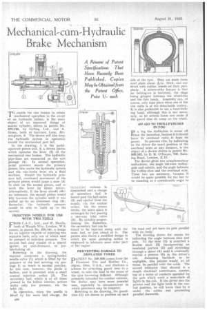
of an hydraulic failure, is the main object of an unproved design of master cylinder, shown in patent No. 570,186, bY Girling, .Ltd., and A. Green, both of Garrison Lane, Birmingham, 9. The device will also keep the hydraulic system in operation should the mechanical part fail.
In the drawing, 1 is the pedaloperated piston and, 2, a driven piston which operates the lever (3) of the mechanical rear brakes. The hydratilie pipe-lines are connected to the exit passage (4). In normal operation, pedal pressure moves the primary . piston; this works the hydraulic system and the rear-brake lever via a fluid medium. Should the hydraulic pressure fail, continued movement of the primary piston would cause a nose (5) to abut on the second piston, and so work the lever by direct action. Alternatively, if the lever should offer no resistance, the second piston would idly traverse the cylinder until it was pulled up by an abutment ring (6); thereafter, the hydraulic pressure • wonld he able to build up to the • normal, INJECTION NOZZLE FOR USE WITH TWO FUELS
FROM C.A.V., Ltd., and W. Nicolls, .both of Warple Way, London, W.3, Comes, in patent No. 570,161, a design for an injector capable of injecting two separate fuels, only one of which need be pumped at injection pressure. The second fuel may consist of a special igniter, an anti-detonant, or just lubricating oil.
Referring to the drawing, the injector comprises a spring-loaded needle-valve (1) which is lifted by the pressure of the fuel arriving via passage 2; so much is normal practice. In this case, however, the pintle is hollow, and is provided with a small central injection orifice (3). The secondary fuel, which is at all times present in the hollow interior, arrives under only low pressure, via the • inlet (4).
In operation, when the needle is lifted by the main fuel charge, the interior volume is diminished and a charge of secondary fuel is forced past the ball-valve (5) and ejected from the nozzle, via the central orifice. On the return stroke, the inner space is recharged by fuel passing a one-way inlet valve (6) By suitably proportioning the diameters, the secondary fuel can be timed to be injected along with the main fuel, or just ahead of it. The patent also shows a modified design in which the same pumping action is employed to lubricate some other part of the engine.
PREVENTING DAMAGE TO DEFLATED TYRES DATENT No. 560,686 comes from the
Firestone Tire and Rubber Co., Akron, Ohio, U.S.A., and discloses a sc&me for attaching guard rims to a wheel, to take the load in the event of the tyre becoming deflated. Although primarily intended for combat vehicles, the device may have more peaceful uses especially in circumstances in , which punctures may be frequent.
Referring to the drawing, the guard. rims (1) are shown in position on each side of the tyre. They are made from steel plate about -prin. thick, and are fitted with rubber treads on their periphery. A noteworthy feature is that no bolting-on is involved, the rings being gripped between the wheel-rim and the tyre beads. Assembly can, of course, only take place when one of the rim walls is of the detachable variety. It is also preferable to use a bead-locking band, although this is not necessary, as no serious harm can occur if the guard rims do creep on the wheel.
AN AID TO TROLLEYBUSES IN FOG
IN a fog the trolleybus is worse off than the motorbus, because if it should leave its overhead cable it loses its power. To prevent this, by indicating to the driver the exact position of the overhead wires at any moment, is the object of a device shown in patent No. 569,542, by D. M. O'Dwyer, 760, I3arking Road, London, E.13.
The device gives two complementary indications, the angle between trolleypole and vehicle, and the angle between the trolley-shoe and the overhead wire. These two are necessary, because it would be quite possible for the bus to be standing at a considerable angle to the road and yet have with its body.
The drawing shows the 'means for indicating the angle between shoe and pole. To the shoe (1) is attached a flexible shaft (2) incorporating an insulated portion (3) and extending through a sleeve (4) until it eventually reaches a pointer (5) in the driver's cab. Assuming backlash to be negligible, this pointer would, at all times, lie parallel with the cable. The second indicator (not shown) is a simple electrical contrivance, consisting of a series of contacts operated by the pole which work a semi-circle of lights in the cab. If the driver sees the pointer and the light both in the central position, he will know that he is under the cables and proceeding parallel therewith.•/