


SIX-WHEEL DRIVE AND FOUR-WHEEL STEERING.
Page 64
If you've noticed an error in this article please click here to report it so we can fix it.
A Wesuind of Recently Published Patent Specifications.
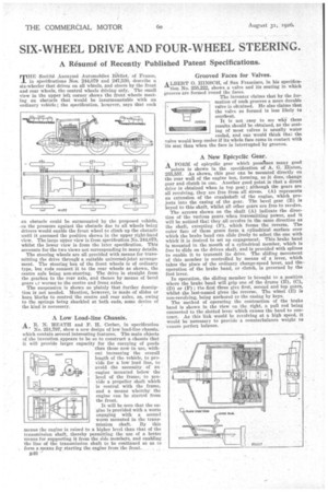
THE Socike Ationyine Automobiles Be'rliet, of France, in specifications Nos. 244,079 and 247,530, describe a six-wheeler that drives on all wheels, and steers by the front and rear wheels, the central wheels driving only. The small view in the upper left corner shows the front wheels meeting an obstacle that would be insurmountable with an ordinary vehicle ; the specification, however, says that such
en obstacle could be surmounted by the proposed vehicle, • is the pressure against the obstacle due to all wheels being drivers would enable the front wheel to climb up the obstacle intil it assumed the position shown in the upper right-hand view. The large upper view is from specification No. 244,079, whilst the lower view is from the later specification. This accounts for the two views not corresponding in many details. The steering wheels are all provided with means for transmitting the drive through a suitable universal-joint arrangement. The steering box of the front wheels is of ordinary type, but rods connect it to the rear wheels as shown, the centre axle being non-steering. The drive is straight from the gearbox to the rear axle, and thence by means of bevel gears Li. worms to the centre and front axles.
The suspension is shown so plainly that further description is not needed. Mention, however, is made of slides or horn blocks to control• the centre and rear axles, as, owing to the springs being shackled at both ends, some device of the kind is necessary.
A Low Load-line Chassis.
AB. N. HEATH and F. H. Corber, in -specification
No. 251,797, show a new design of low load-line chassis, which contain .several interesting features. The main objects of the invention appears to be so to construct a chassis that it will provide larger capacity for the carrying of goods than those now in use, without increasing the overall length of the vehicle, to provide for a low load line, to avoid the necessity of an engine mounted below the level of the frame, to provide a propeller shaft which is central with the frame, and a means whereby the engine can be started from the front.
It will be seen that the engine is provided with a worm engaging with a second worm mounted in the transmission shaft. By this means the engine is raised to a higher level than that of the transmission shaft, thereby permitting the use of a better means for supporting it from the side members, and enabling the line of the transmission shaft to be continued so as to form a means for starting the engine from the front.
MSG, Grooved Faces for Valves.
ALBERT 0. HINSCH, of San Francisco, in his specification No. 255,222, shows a valve and its seating in which grooves are formed round the faces. The inventor claims that by the formation of such grooves a more durable valve is obtained. He also claims that the valve so formed is less likely to overheat.
It is not, easy to see why these results should be obtained, as the seating of most valves is usually water cooled, and one would think that the valve would keep cooler if its whole face came in contact with its seat than when the face is interrupted by grooves.
25222
A New Epicyclic Gear.
A FORM of epicyclie gear which possesses many good
points is shown in the specification of A. G. Hinton, 255,557. As shown, this gear can be mounted directly on the rear wall of the engine box, forming, as it does, change gear and clutch in one. Another good point is that a direct drive is obtained when in top gear ; although the gears are all revolving, they are free from all stress. (A) represents an extension of the crankshaft of the engine, which projects into the easing of the gear. The bevel gear (B) is keyed to this shaft, whilst all other gears are free to revolve.
The arrows shown on the shaft (A) indicate the direction of the various gears when transmitting power, and it will be noticed that they all revolve in the same direction as the shaft, excepting (F), -which forms the reverse. The outer face of these gears form a cylindrical surface over which the brake band can slide freely to select the one with which it is desired to set up engagement. This brake band is mounted in the mouth of a cylindrical member, which is free to slide on the driven shaft, and is provided with splines to enable it to transmit its drive. The sliding movement of this member is controlled by means of a lever, which takes the place of the ordinary change-speed lever, and theoperation of the brake band, or clutch, is governed by the foot lever.
In operation, the sliding member is brought to a position where the brake band will grip one of the drums (B), (C), (D) or (F) ; the first three give first, second and top gears, whilst the last-named gives the reverse. The wheel (E) is non-revolving, being anchored to the casing by keys.
The method of operating the contraction of the brake band is shown in the view on the right, a pull rod being connected to the slotted lever which causes the band to contract. As this link would be revolving at a high speed, it would be necessary to provide a counterbalance weight to ensure perfect balance.