


THE BRYAN WATER-TUBE BOILER.
Page 28
If you've noticed an error in this article please click here to report it so we can fix it.
A Resume of Recently Published Specifications.
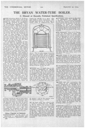
SOME interesting details of the Bryan water-tube steam boiler used on the agricultural tractor which is similarly named, are disclosed in specification No. 220,509, by G. A. Bryan. There are two U-shaped castings; one at each side of the boiler. The bases of -these U-shaped pieces are the lower portions of the boiler ; the headers are two cylindrical drums. The headers and bottom portions, besides opening directly into one another through the medium of the legs of the U's, are Also connected by a nest of tubes arranged in zig-zag fashion between them. There • are really• two sets, of these tubes; one set communicates between "the water spaces at one side of the boiler, and the other between the other two spaces.
The arrangement is worthy of note, and may best be explained by considering a single tube of a set. It starts at its connection with the upper side of the bottom water space, and is thence led across to the other side, sloping gently upwards. At the other side of the boiler. it is turned back upon itself and led to the side from which it. started, still sloping upwards. This process is continued through half-a-dozen complete double turns before the tube reaches the water space, to which it is connected, as to the bottom one, by means of a special form of tapering joint, so designed that each pair of tubes is held in the header by a single bolt and clamp.
Above the two cylindrical drums which form the headers is another which serves as the steam drum. The steam is led from the upper part of the headers through pipes which enter the steam drum at the top, and which terminate well within that drum, their outlet ends pointing downwards so that the steam is projected towards the bottom of the drum, where it deposits any water which it. may hold in suspension. A drain pipe is provided to lead this water, and ally other which may condense in the steam drum, back again into the headers. Other tubes, which are practically straight and vertical, and which are
arranged outside the coils of tubes which have been described, communicate with the two water spaces on each side. They are separated from the coils by sheets of asbestos, so that whilst the coils are exposed to the direct heat af the flame by which the water is bleated, the others are comparatively cool, and thus encourage the circulation of the water which runs down the cool outer tubes, and climbs up the inner and hot ones.
Other Patents of Interest.
IMPROVEMENT in the means of lubricating a speed-reducing gear already patented is described in specs48 fication No. 220,389, by L. Burn. The gear itself is rather interesting. The driving shaft has at its inner end a double crank of Comparatively short throw. The two pins engage trai averse slots in a disc which, were it mounted on a shaft in line with the driving shaft, would serve the purpose of an Oldham coupling, half of which it closely resembles. As it is not on a shaft in line with the driver, however, but on one which is displaced to the extent of the throw of the cranks on that driving shaft, there is a reduction in speed from driver to driven, of fifty per cent.
TIPPING gear of simple type is described in specification No. 220,165, by B. A. Dixon. The body is mounted to run on rails fixed on the chassis and so arranged that the body remains in a horizontal or nearly horizontal position as it moves along the rails until its centre of gravity is practically over the ends of the rails. The body is then free to tip about one pair of the rollers on which it is mounted and which come
up against a stop at the moment when the tipping position is reached.
IN the band brake gear which is described in specification No. 220,021, by W. G. Wilson, the lining is split eircumferemially. One piece is attached to the band I one end only. The other piece is not attached at ail, but is anchored to a separate bracket, located at 180 deg. distant from the anchorage of the band. The inventor claims that by this construction he eliminates much of the inequality of braking effort which is a frequent fault in brakes of this description.
ANOTHER brake patent is described in Specification No. 220,468,. by L. Saunion. It is concerned with brakes for the front wheels, and the inventor claims that by the adoption of his construction, in which the operating mechanism of the brake is actually, mounted on the top of the steering pivot, the braking effect is undisturbed, whatever may be the movement of the steering gear.
THE PRIMARY object Of T. Barty,
and the Westinghouse Brake and Saxby Signal Co., Ltd., in the invention which is described by them in specification No. 220,425 has been to provide s simple means of control for fluid pres, sure braking apparatus for use on auto mobile vehicles. A plain disc valve,controlled by a hand lever, has, besides through Ports of ample diameter, narrow grooves by the aid of which a graduated pressure may be provided in the brake cylinder. The inventors also refer to a means of ensuring that a predetermined pressure on the brake cylinder is nob exceeded, including means of warping the driver that this safety valve is in operation.
BRAKE linings of the woven type, made according to the ideas of P. G. Kenyon, as disclosed in specification No. 220,168 will be reinforced by a core of metal which may be extended beyond the end of the lining so as to serve as means of securing the lining to its shoe.
IN the sparking plug which is described in specification No. 220,397, by W. H. Duffety and for which the claim is made that it. is particularly capable of resisting the short-circuiting action of carbonized oil, the central electrode is made to clear the interior of the insulator for about one-half its length, and is also formed with a collar, below the bottom of the electrode insulator, which serves as a baffle to prevent oil or other material being blown intothat clearance _space.
WHEEL and axle construction for
trailers is the subject-matter of patent specification No. 216,644, by J. Atkinson. Each wheel is keyed on to a separate stub axle, which is mounted in appropriately spaced roller bearings which are themselves carried in an oil. bath casing which is fastened to the underside of the wagon bolster. As shown in'the drawing which accompanies the patent specification the casing is secured by the bolts which attach the springs. Oil-conveying rings are mounted on the body of the stub axles, to pick up the oil which is in the casing and lift it to the upper side of the shaft, and the easing is equipped with an oil-filling orifice and pipe.
CERTAIN modifications in the design
of his " unidirectional driving mechanism" are described in specification No. 217,684, by G. Constantinesco._ The spring controlling the ratchet mechanism which acts on the rotor of the gear is subjected to a permanent force acting towards an external point other than a point on the rotor, and provision is made for reversing the gear.