


Patents Completed.
Page 22
If you've noticed an error in this article please click here to report it so we can fix it.
Oil Engine Control. Daimler Differential Lock. Mossay Tractor.
Copies of complete specifications of the patents published on this page can be obtained from the Sales Branch, Patent Office, Holborn, W.C., at the cost of sixpence for each specification.
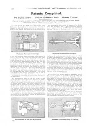
P... A. H. MessAv, No. 20,606, dated 6th October, 1914. Thetractor illustrated in the accompanying drawings is designed for use with trailers which can be used independently of it if desired. The tractor is driven and steered on a front pair of wheels, and a single small wheel supports its frame at the back, this wheel being situated on the centre line of the tractor. The tractm framework is circpped, so that it, can rasa beneath the trailer with the rear wheel, and it is also provided with channel casings at each side near the ground to take the front wheels of the trailer. This arrangement of tractor is particularly convenient for manoeuvring, and for coupling it up to a trailer it is backed underneath it until the trailer front wheels are near the channels which receive them. The tractor brakes are then put on, and the trailer drawn forward by a winch behind the driver's seat until the rear wheels of the trailer are in line with the small rear wheel of the tractor. This arrangement facilitates the steering. The tractor may be tied by side chains al its rear end to the trailer.
An alternative construction is described and illustrated in the. specification.
Soc. ARQITEMBOTJRG JORET ET CIE, Na, 17,886, of 1914, dated under International Convention, 21st August, 1913.— This carburettor is designed to prevent the accumulation of fuel above the throttle valve, which occurs when running with the throttle nearly closed. The mixing chamber is inclined downward from the horizontal towards the throttle valve, and the fuel jet is inclined from the vertical also towards the throttle valve. On the engine-side of the valve a small passage is formed which provides for commimication from the lower part of the interior of the valve to the induction pipe. The action of this device in preventing accumulation of fuel is illustrated in the drawing. Any fuel which is not atomized on leaving the jet flows into the valve casing, and is there atomized by a jet of air passing through the special passage on the engine side of the valve.
THE DAIMLER CO, Lam., and A. E. BERRIMAN, No, 22,816,
dated 20th November, 1914. The accompanying drawing shows a method of locking the differential on a worm-driven rear-axle. The hub of the worm-wheel is extended beyond the hub of the bevel-wheel, and reduced in size so as to form a virtual continuation of it. The drive is taken from the bevel wheel to an internal-castellated shaft, and the smaller part of the hub of the worm-wheel is provided with grooves which can engage these castellations when the shaft is moved longitudinally; such movement then locks the shaft directly to the worm-wheel, and by fitting this device on both sides of the differential the latter can he put out of operation.
The longitudinal movement of the shaft is given to it by unscrewing the hub-cap on the wheel, this cap being provided with claws to engage a flanged stud on the end of the shaft. Suitable stops are provided to limit the movement, of the shaft to the necessary amount.
H. R.. CLARK, No. 19,554, dated 8th September, 1914.— This invention relates to two-stroke engines in which the fuel is injected at or near the end of the stroke, and comprises means for regulating the quantity of fuel according to the amount of air which is drawn or forced into the cylinder. The air inlet is shown at the bottom on the right-hand side, and is controlled by a grid valve operated by hand. After passing the valve the air enters a chamber adjacent to the cylinder, and passes into the cylinder by way of the usual valve ports. This chamber is in communication with one end of a cylinder shown at the top on the right-hand side, and a piston in this cylinder is free to move under the joint action of the atmosphere on one side, and a spring and the air inlet pressure on the other side. This piston is connected to the usual form of adjustablethrow pump which supplies the fuel to the cylinder. When the air inlet is throttled the fuel supply is reduced, so that the proportions of the mixture remain constant.